

What Is UML? A Short History, the 14 Diagrams of UML 2.5.1 and Which Ones You Will Actually Use
UML is the OMG's standard modeling language for putting the model scattered through your code into a notation everyone reads the same way; its current version is UML 2.5.1 from 2017, which defines 14 diagrams, 7 structure and 7 behavior. A short history from the method wars, the diagrams people actually use, the difference between model and diagram, and Fowler's sketch, blueprint and programming language modes.
Version note: The diagrams in this post use UML 2.5.1 notation; the C# examples were tested with .NET 10.
Guess First
The leave module of an HR (Human Resources) portal has a request that covers 5 working days, so it needs the manager's approval and then the director's. The employee submits it, the manager approves it, and then the employee changes their mind and cancels. A day later the director clicks the approve link in an old notification e-mail. What does the last line print?
LeaveRequest request = new(id: 42, workingDays: 5);

request.Submit();
request.Approve();   // the manager approves
request.Cancel();    // the employee backs out
request.Approve();   // the director clicks the link in an old e-mail

Console.WriteLine(request.Status);

public enum LeaveStatus { Draft, PendingManagerApproval, PendingDirectorApproval, Approved, Rejected, Cancelled }

public sealed class LeaveRequest(int id, int workingDays)
{
    public int Id { get; } = id;
    public int WorkingDays { get; } = workingDays;
    public LeaveStatus Status { get; private set; } = LeaveStatus.Draft;

    public void Submit() => Status = LeaveStatus.PendingManagerApproval;

    public void Approve() =>
        Status = Status == LeaveStatus.PendingManagerApproval && WorkingDays > 3
            ? LeaveStatus.PendingDirectorApproval
            : LeaveStatus.Approved;

    public void Cancel()
    {
        if (Status != LeaveStatus.Approved)
            Status = LeaveStatus.Cancelled;
    }
}
The answer is below. Before you scroll, try to sketch in your head which state the request can move to from which other state, using only the code.
The Model Hidden in the Code
ApprovedA cancelled request got approved. Payroll will count this leave, it will be written to the calendar, and the employee's balance will shrink even though they never took the days off. There is no compiler error and no warning. Approve() only thinks "if it is waiting for the manager and longer than 3 days, send it to the director"; in every other state it approves. Cancel() happily cancels a request that is still a draft.
The interesting part is not the bug but why it slipped through. These 30 lines contain a model: six states and the transitions between them. But the model is scattered through the code. No line answers the question "which state can go to which?"; you have to read every method and assemble the answer in your head. Had the same information been drawn as a state machine diagram, you would have seen at a glance that no "approve" arrow leaves the Cancelled box. In code review someone would have asked "where is this arrow?"
Here is a corrected version in which every arrow of the diagram becomes one case:
LeaveRequest request = new(id: 42, workingDays: 5);

request.Submit();
request.Approve();
request.Cancel();

try
{
    request.Approve();
}
catch (InvalidOperationException ex)
{
    Console.WriteLine(ex.Message);
}

Console.WriteLine(request.Status);

public enum LeaveStatus { Draft, PendingManagerApproval, PendingDirectorApproval, Approved, Rejected, Cancelled }

public sealed class LeaveRequest(int id, int workingDays)
{
    public int Id { get; } = id;
    public int WorkingDays { get; } = workingDays;
    public LeaveStatus Status { get; private set; } = LeaveStatus.Draft;

    public void Submit() => Status = Status == LeaveStatus.Draft
        ? LeaveStatus.PendingManagerApproval
        : throw Invalid(nameof(Submit));

    // Every arrow in the diagram is a case; no arrow means an exception
    public void Approve() => Status = Status switch
    {
        LeaveStatus.PendingManagerApproval when WorkingDays > 3 => LeaveStatus.PendingDirectorApproval,
        LeaveStatus.PendingManagerApproval => LeaveStatus.Approved,
        LeaveStatus.PendingDirectorApproval => LeaveStatus.Approved,
        _ => throw Invalid(nameof(Approve))
    };

    public void Cancel() => Status = Status switch
    {
        LeaveStatus.PendingManagerApproval or LeaveStatus.PendingDirectorApproval => LeaveStatus.Cancelled,
        _ => throw Invalid(nameof(Cancel))
    };

    private InvalidOperationException Invalid(string action) =>
        new($"Request {Id}: '{action}' is not allowed in status {Status}.");
}
Request 42: 'Approve' is not allowed in status Cancelled.
CancelledThis version is still incomplete: according to the requirements an approved leave can be cancelled before it starts, which needs a date check. We will come back to that in the State Machine post. The point of this post is this: there is always a model inside the code, and UML (Unified Modeling Language) is the way to put that model in front of everyone, separate from the code, in a notation everyone reads the same way. If you want the database side of why a status field should not be updated from everywhere, the Solution Patterns series post "When the Status Column Is Updated from Everywhere" solves the same problem with a transition table.
What UML Is and What It Is Not
UML is a standard modeling language for specifying, visualizing and documenting software systems, maintained by the OMG (Object Management Group). The word "language" matters: UML has a notation (boxes, arrows, diamonds, stick figures) and, behind it, a metamodel that defines what each element means. The line - startDate: DateOnly [1] in a class box is not free-form text; the specification defines it as a property with a visibility, a name, a type and a multiplicity. That is why two different teams can read the same diagram the same way.
UML is not a process or a methodology. It does not tell you which diagram to draw when, who approves it or how many to draw. RUP (Rational Unified Process), often mentioned alongside UML in the 2000s, was a separate process proposal; mixing the two up is one of the reasons UML got its "heavy and bureaucratic" reputation. UML is not a tool either: you can use the same notation on paper, on a whiteboard, in a text-based tool such as PlantUML or in a large modeling tool.
The current formal version is UML 2.5.1, published by the OMG in December 2017 (document number formal/17-12-05); no newer formal version has appeared since. The specification is about 800 pages. Nobody learns UML by reading it cover to cover, but it has the final word in a notation argument. Whenever this series says "UML says", that document is the source.
A Short History: From the Method Wars to UML 2.5.1
In the early 1990s there were dozens of methods for object-oriented analysis and design, each with its own notation. The three most widespread were Grady Booch's Booch method, OMT (Object Modeling Technique), published by James Rumbaugh and his team in 1991, and Ivar Jacobson's OOSE (Object-Oriented Software Engineering), which put the use case at the center. Booch drew a class as a cloud, OMT as a rectangle; two people on the same team using two notations could not read each other's diagrams. The period later became known as the "method wars".
In October 1994 Rumbaugh joined Rational Software, where Booch worked, and the two started merging their methods. Jacobson joined in 1995, which is why the three are called the "three amigos". UML 0.9 came out in June 1996, UML 1.0 was submitted to the OMG as a standard proposal in January 1997, and UML 1.1, extended with contributions from other companies, was adopted by the OMG as a standard in November 1997. In the following steps it also became a joint standard of the ISO (International Organization for Standardization) and the IEC (International Electrotechnical Commission) twice:
| Version | Year | What changed |
|---|---|---|
| UML 1.1 | 1997 | First OMG standard; 9 diagram types |
| UML 1.4.2 | 2005 | Became an international standard as ISO/IEC 19501:2005 |
| UML 2.0 | 2005 | Major revision: combined fragments in sequence diagrams, new diagram types, 13 diagrams |
| UML 2.2 | 2009 | Profile diagram became a separate type; 14 in total |
| UML 2.4.1 | 2011 | Published as ISO/IEC 19505-1 and 19505-2:2012 |
| UML 2.5 | 2015 | Infrastructure and Superstructure merged into one document, text simplified; metamodel technically equivalent to 2.4.1 |
| UML 2.5.1 | 2017 | Bug fixes; still the current formal version today |
You may meet the ISO/IEC numbers in corporate tenders and contracts; in daily work "UML 2.5.1 notation" is enough. The practical lesson from the table: a large share of the UML examples you find online date from the UML 1.x era. If a sequence diagram shows branching arrows instead of alt and loop boxes, or you read the name "collaboration diagram", you are looking at an old source. UML 2.0 renamed the collaboration diagram to communication diagram.
14 Diagrams: Structure and Behavior
Annex A of the UML 2.5.1 specification groups the diagrams in a taxonomy. The first split is simple: structure diagrams show the time-independent structure of the system (what exists and what it is connected to), behavior diagrams show what happens over time (who does what, in which order, which state comes next). Inside behavior, the four diagrams that focus on messages between objects are grouped again as "interaction diagrams".
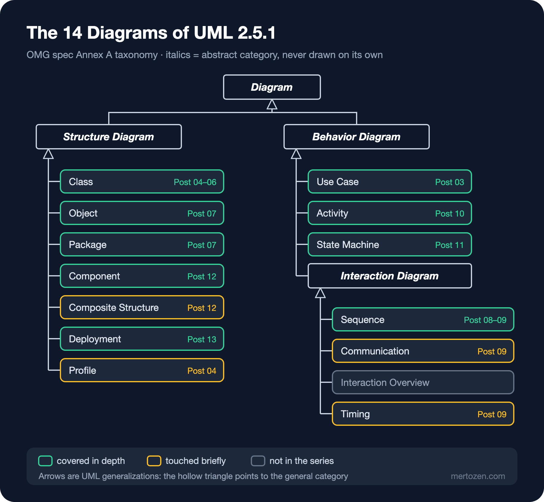
The arrows in the figure are UML too: a hollow triangle means generalization, so "a Class Diagram is a Structure Diagram". The four boxes in italics are abstract categories; you cannot "draw a structure diagram", only one of its kinds. Here is the question each diagram answers, in one sentence:
- Class: which concepts exist, what information do they carry, how are they related? Object: what are the concrete instances of these concepts at a given moment? Package: into which groups is the code divided and how do the groups depend on each other?
- Component and Composite Structure: which replaceable parts make up the system and through which interfaces do they talk? Deployment: which part runs on which machine or container? Profile: how did you extend UML for your own domain?
- Use Case: who uses the system and for what goal? Activity: which steps, decisions and parallel branches does a workflow go through? State Machine: which states does an object go through, and which event moves it to which state?
- Sequence: in a scenario, who calls whom and in what order? Communication: in the same interaction, who is linked to whom? Interaction Overview: how do several interactions combine into a flow? Timing: when do state changes happen on a time axis?
The taxonomy is not a rigid rule; the specification does not forbid mixing elements of different kinds in one diagram. Two important guests of this series are also missing from the tree: the C4 (Context, Container, Component, Code: Simon Brown's approach to describing software architecture at four zoom levels) model and the ER (Entity-Relationship) diagram are not part of UML, but in architecture and data modeling they are used more often than UML. The series gives each of them its own post.
Which Ones Will You Actually Use?
You are unlikely to meet a team that actively uses all 14 diagrams. The best documented evidence is Marian Petre's "UML in Practice" study presented at ICSE (International Conference on Software Engineering) 2013. Petre interviewed 50 professional developers from 50 companies: 35 did not use UML, none used it "wholeheartedly", and 11 used it selectively. The diagrams these selective users relied on most were, in order, class, sequence and activity diagrams; state machine and use case diagrams were at the bottom of the list. This is a qualitative interview study, not a survey, so generalizing the percentages would be wrong. But the picture matches what I see in the field: UML is used where it helps, piece by piece, adapted to the audience.
The seven diagrams this series focuses on are use case, class, object/package, sequence, activity, state machine and component/deployment. The selection criterion is "which question does a .NET team ask on a real project that makes it need this diagram". The class diagram helps when discussing the domain model and Entity Framework Core (EF Core) entities, the sequence diagram when talking about which layers an API (Application Programming Interface) request passes through, the state machine when pinning down the rules of a status field, deployment and C4 when explaining the system to a newcomer. Timing and interaction overview diagrams are valuable in their niches (embedded systems, protocol design), but in an HR portal you will rarely need them; we will meet them briefly in the sequence diagram posts.
Model and Diagram Are Not the Same Thing
This is the most frequently missed distinction in UML. The model is a single structure that holds every element of the system (classes, relationships, states, messages). A diagram is a window onto part of that model.
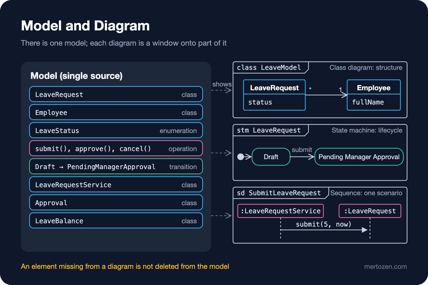
The LeaveRequest class is defined once in the model. It appears as a box in the class diagram, as the owner of the lifecycle in the state machine diagram and as a lifeline in the sequence diagram; all three look at the same element. The specification defines that every diagram can have a frame whose heading in the top-left corner states the kind of diagram and what it shows: stm LeaveRequest for a state machine, sd SubmitLeaveRequest for a sequence diagram, uc for use case, act for activity. The frame headings in the figure use this notation.
The distinction has practical consequences. First, leaving an element out of a diagram does not delete it from the model. If your sequence diagram does not show IBalanceService, that does not mean the system has no balance check; it means it is a detail you did not want to discuss in that scenario. Second, in a model-based tool (such as Enterprise Architect or MagicDraw) renaming a class updates every diagram that shows it, while in a drawing tool (such as draw.io) each diagram is an independent picture and consistency is your job. Third, treating the code as "the real model" and keeping diagrams as windows derived from or looking at the code, as this series will do, is also a legitimate choice. Then the LeaveStatus enum in the code is the model itself and the diagram is a readable view of it.
Fowler's Three Modes and Where This Series Stands
In his 2003 "UmlMode" article Martin Fowler explains why people cannot agree about UML: they use it for three different purposes. He notes that Steve Mellor arrived at the same split independently.
In sketch mode a diagram is for thinking and explaining. It is selective: only the part that matters for that conversation is drawn. It is used in a ten-minute design discussion at the whiteboard (forward sketching) or when explaining existing code to a newcomer (reverse sketching). Fowler's sentence for this mode sticks: "comprehensiveness is the enemy of comprehensibility". Not every notation rule has to be followed; the goal is communication.
In blueprint mode a diagram is a complete design document: a designer draws it and a programmer can turn it into code without much thought. This mode needs tool support and notation accuracy, and keeping the model in sync with the code takes real effort. In programming language mode UML itself is executable code; MDA (Model Driven Architecture) and fUML (Foundational UML) are examples of this line. Fowler always viewed this mode with skepticism, and this series leaves it out of scope.
This series sits between sketch and "blueprint close to the code". We draw diagrams with correct notation but only as detailed as needed to answer one question; we show what each diagram element corresponds to in C# and .NET 10 code; in the last posts we keep diagrams as text in the repo (PlantUML and Mermaid). The whole series uses a single case: the "Leave Request" module of a fictional HR portal. An employee opens a leave request, their manager approves or rejects it, requests longer than 3 working days go on to the director, approved annual leave is deducted from the balance and written to the calendar, and cancellation has its own rules. In the next post we write these requirements down item by item and extract a model from them; after that we carry the same case from use cases to classes, from sequences to state machines and from deployment to C4.
Common Pitfalls
Seeing UML as all or nothing. Many teams never use UML because they think it means drawing all 14 diagrams completely. Yet a single state machine diagram can let a review catch a bug like the cancelled request that got approved above. A diagram is worth exactly as much as the question it answers.
Drawing with old notation. Booch clouds, the branching sequence arrows of UML 1.x or the term "collaboration diagram" mislead today's readers. Check when a source was written; verify any notation you are unsure about in the UML 2.5.1 specification or in a spec-based reference such as uml-diagrams.org.
Mistaking the diagram for the model. A relationship missing from a diagram does not prove the relationship does not exist in the system. When reading, always ask "which question was this diagram drawn to answer?"; when drawing, write that question in the heading or the caption.
Mixing the modes. Reading a sketch as a blueprint ("Employee has no Email here, so we won't store it") or sharing a whiteboard photo where a blueprint is expected disappoints both sides. When you share a diagram, say which mode you drew it in.
Ignoring the notation because "it's only a sketch". Sketch mode allows flexibility, but a hollow diamond and a filled diamond, a solid arrow and a dashed arrow say different things. A wrong arrow means wrong code. That is why the class diagram posts of this series show the C# equivalent of every arrow one by one.
A Small Experiment
★☆☆ For the LeaveRequest in the first listing, draw six boxes on paper (one per LeaveStatus value) and an arrow for every transition the code allows. How many arrows did you get? Which ones should not exist according to the requirements?
★★☆ Add a Reject(string reason) method to the corrected code: only the two pending states may move to Rejected, and an empty reason is refused. Draw the arrows first, then write the switch, and try it with a line that rejects a cancelled request.
★★★ Find a design document or wiki page written in your project in the last six months. Name the kind of each diagram in it according to the taxonomy in this post, and note for each one which of Fowler's three modes it was drawn in and whether it still matches the code.
In the next post we write the requirements of the HR portal's leave module and try to extract a model from them: from nouns to candidate classes, from verbs to use cases and operations, from sentences starting with "if" to activity and state machine diagrams. Then comes a table that matches every diagram type with the question it answers, and the map of the series.