

Activity Diagrams: Actions, Decisions, Fork/Join, Swimlanes and Modeling an Approval Workflow
An activity diagram draws a workflow as steps, guarded decisions, parallelism with fork/join and swimlanes showing who does what; its semantics is token flow, so paths leaving a decision that do not meet in a merge get stuck in an implicit join. The post draws the HR Portal leave approval process with swimlanes, demonstrates the token rules with a small C# simulator and splits the flow into handlers.
Version note: The diagrams in this post use UML (Unified Modeling Language) 2.5.1 notation; the C# examples were tested with .NET 10 and the PlantUML code with PlantUML 1.2026.9.
Guess First: Why Was #43 Never Approved?
The HR Portal analyst drew the approval process on the whiteboard: the manager reviews the request, and a decision node asks "is it longer than 3 working days?" If yes, the flow goes to the director's review; if not, straight to a "Mark approved" action. The arrow leaving the director's review also enters the same "Mark approved" box. Two arrows go into the box, both lead to the same place, and the drawing looks clean.
To validate the diagram, the team wrote a small model of UML activity semantics (a "token game"); the edges of the drawing, one to one:
int workingDays = 2; // #43: 2 working days, no director approval needed

new TokenGame([
    new(start, review), new(review, needsDirector),
    new(needsDirector, directorReview, () => workingDays > 3), new(needsDirector, markApproved, () => workingDays <= 3),
    new(directorReview, markApproved), .. tail
]).Run(start);
What happens when Ada's two-day excuse leave #43 goes through this flow? Does "Mark approved" run? If not, where does the token stay?
The Answer: The Token Gets Stuck
== without merge ==
fire ManagerReview
fire NeedsDirector?
stuck: 1 token(s) waiting on NeedsDirector? -> MarkApproved
"Mark approved" never ran. According to the Activities clause of UML 2.5.1, an action with more than one incoming control flow edge does not start until a token has arrived on each of them; the box secretly behaves like a join (implicit join). A decision, on the other hand, offers its token to only one edge. The result: one edge has a token, the other does not, and the action waits forever. Give the same model the two paths joined by a merge node and the flow completes:
== with merge ==
fire ManagerReview
fire NeedsDirector?
fire Merge
fire MarkApproved
fire Fork
fire DeductBalance
fire AddToCalendar
fire Join
fire end
activity finished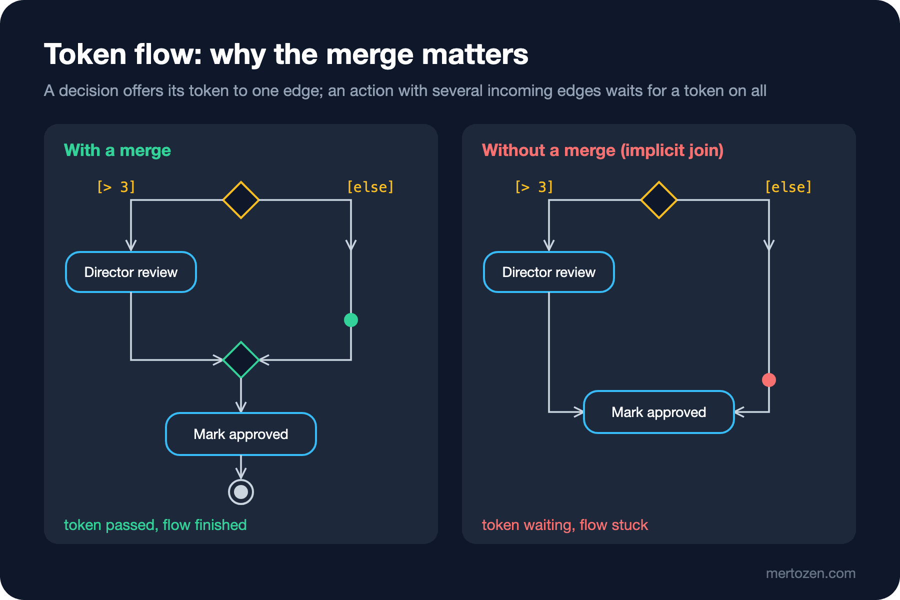
In real life this bug is not in the code but in the heads of the people reading the diagram: one reads "if two arrows come in, wait for both", another reads "whichever arrives". Activity diagram notation has a semantics precisely to remove that kind of ambiguity: token flow. In this post we look at that semantics, the notation, the swimlane diagram of the leave approval process, and how it splits into code.
What Does an Activity Diagram Answer?
A sequence diagram answers "who sends which message to whom, in what order, in this scenario?", and a state machine diagram "which states does an object go through?". An activity diagram answers "through which steps, under which conditions and with what parallelism does the work progress, and who does each step?" The focus is not on objects but on the work itself. That makes it the right tool for discussing a process with the business, showing the flow of an algorithm, or seeing on one page a workflow that lasts days and is touched by several people.
With UML 2, activity semantics were based on a token model similar to Petri nets: nodes take and give tokens, edges carry tokens. This semantics makes the diagram not an "approximate drawing" but a definition precise enough to execute; the simulator in the opening was written with exactly these rules.
Notation
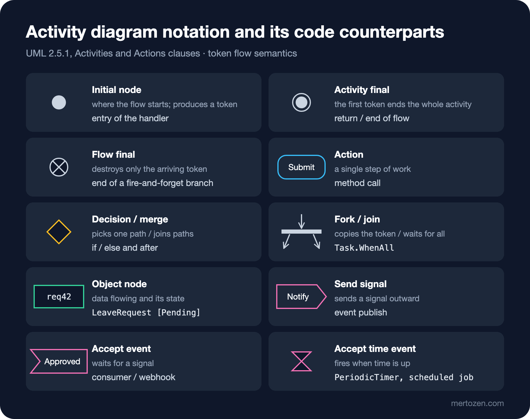
The initial node (filled circle) starts the flow. An action (rounded rectangle) is a single step of work. A decision node (diamond) splits one incoming edge into several outgoing edges with guards; the token passes only through the edge whose guard is true. Guards must exclude each other and cover every case, which is why [else] is so handy. A merge node is also a diamond but does the opposite: it passes every token arriving on any of several incoming edges to its single outgoing edge, without waiting.
A fork node (thick bar) copies the incoming token for each outgoing edge; the branches are now parallel. A join node (also a thick bar) waits for a token on every incoming edge, then emits a single token. An activity final (a circle with a filled ring) ends the whole activity as soon as the first token arrives; tokens on the other branches disappear too. A flow final (a circle with a cross) destroys only the arriving token, and the other branches carry on.
An object node (plain rectangle) shows data flowing; its state can be written in square brackets: LeaveRequest [PendingManagerApproval]. A send signal action (outward pentagon) sends a signal, an accept event action (notched pentagon) waits for a signal, and an accept time event (hourglass) fires when a duration or a point in time is reached. Activity partitions (swimlanes) are the lanes that group steps by who performs them.
The Leave Approval Workflow: With Swimlanes
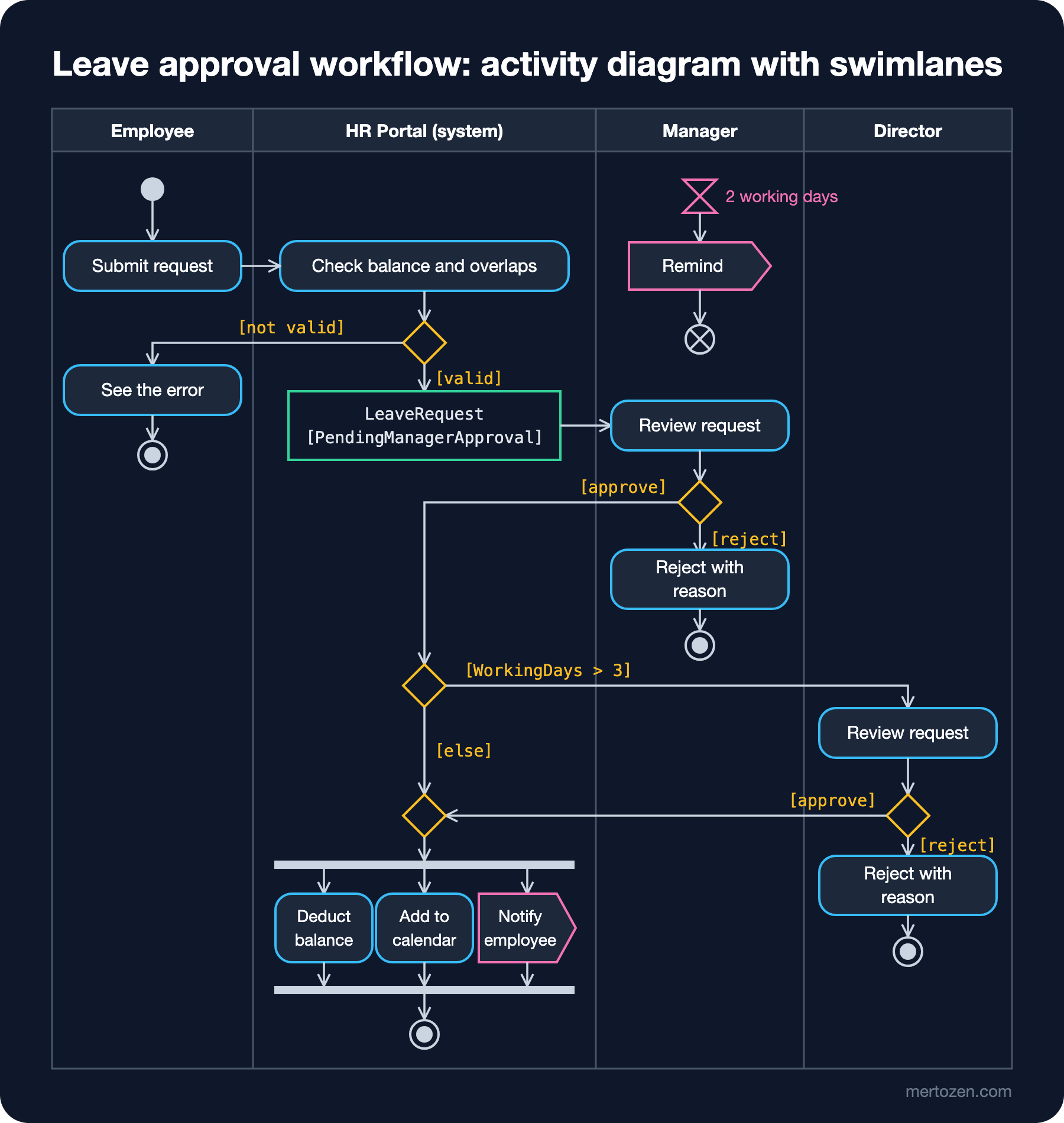
The figure is the approval part of requirements R1–R10. There are four partitions: Employee, HR Portal (system), Manager and Director. The flow starts in the Employee lane, and the system checks balance and overlaps (R3, R4); if the check fails, the employee sees the error and the activity ends. If it passes, an object node appears: the request in the PendingManagerApproval state. The manager reviews the request; the reject branch includes writing a reason (R6) and ends in its own activity final.
The approve branch returns to the system and a second decision is asked: if [WorkingDays > 3], the request moves to the Director lane (R7). The director's approval and the "no director needed" branch meet in a merge; this is exactly where the bug from the opening is fixed. Then a fork opens three parallel branches: deduct the balance, add to the calendar and notify the employee (R9, R10). The join waits for all three, and then the activity ends.
The hourglass at the top of the Manager lane is the reminder rule in R10: an accept time event with no incoming edge is enabled when the activity starts and fires when the time is up. After the "Remind" signal is sent, that flow ends in a flow final. Had we used an activity final, the reminder would kill the whole approval process; the flow final destroys only its own token.
Two things are deliberately missing. There is no lane for the HR specialist, because they have no step in this process; HR takes part in the cancellation (R11) and balance correction (R12) processes. Drawing an empty swimlane makes the reader think "something should have been here". The balance check at approval time (R8) is not drawn either; it appeared in detail in the sequence diagram of the previous post. The activity diagram shows the skeleton of the process, the sequence diagram the inside of a step.
Token Flow: Why Does a Join Wait?
The shortest way to grasp activity semantics is to execute it yourself once. The core of the simulator from the opening:
public enum NodeKind { Initial, Action, Decision, Merge, Fork, Join, ActivityFinal }

public sealed record Node(string Name, NodeKind Kind);

public sealed record Edge(Node From, Node To, Func<bool>? Guard = null);

// a small model of UML activity semantics: tokens wait on edges, nodes fire by their rules
public sealed class TokenGame(IReadOnlyList<Edge> edges)
{
    private readonly Dictionary<Edge, int> tokens = edges.ToDictionary(e => e, _ => 0);

    public void Run(Node initial)
    {
        Offer(initial);
        bool fired = true;
        while (fired)
        {
            fired = false;
            foreach (Node node in edges.Select(e => e.To).Distinct())
            {
                List<Edge> incoming = edges.Where(e => e.To == node).ToList();
                // action and join: every incoming edge needs a token (implicit join for actions)
                bool ready = node.Kind is NodeKind.Action or NodeKind.Join or NodeKind.Fork or NodeKind.ActivityFinal
                    ? incoming.All(e => tokens[e] > 0)
                    : incoming.Any(e => tokens[e] > 0);
                if (!ready) continue;
                foreach (Edge e in node.Kind is NodeKind.Merge or NodeKind.Decision
                             ? [incoming.First(e => tokens[e] > 0)]
                             : incoming)
                    tokens[e]--;
                Console.WriteLine($"fire {node.Name}");
                if (node.Kind == NodeKind.ActivityFinal)
                {
                    Console.WriteLine("activity finished");
                    return;
                }
                Offer(node);
                fired = true;
            }
        }
        foreach ((Edge e, int count) in tokens.Where(t => t.Value > 0))
            Console.WriteLine($"stuck: {count} token(s) waiting on {e.From.Name} -> {e.To.Name}");
    }

    private void Offer(Node node)
    {
        List<Edge> outgoing = edges.Where(e => e.From == node).ToList();
        IEnumerable<Edge> targets = node.Kind == NodeKind.Decision
            ? [outgoing.First(e => e.Guard?.Invoke() ?? true)]
            : outgoing;
        foreach (Edge e in targets)
            tokens[e]++;
    }
}
The rules fit in four lines. Actions and joins require a token on every incoming edge; merges and decisions are satisfied with one token. A decision gives its token to the single edge whose guard is true; other nodes (forks included) give one token to each outgoing edge. An activity final ends everything at the first token. In the "with merge" output, after Fork, DeductBalance and AddToCalendar fire separately, and Join only once both have finished. This model is a simplified version of real UML semantics (no object flows, weights or interruptible regions), but it is enough to show why a join waits and why joining without a merge gets stuck.
We already wrote the C# counterpart of fork/join: the LeaveApprovedConsumer from the previous post starts the calendar entry and the e-mail as two Tasks and waits with await Task.WhenAll(calendarTask, mailTask). Task.WhenAll is a join: it does not continue until every task has finished.
Back to Code: Splitting the Workflow into Handlers
The activity in the figure lasts days and touches four different people; you cannot write it as a single method. The real decision when turning the diagram into code is where the flow "stops and waits". Every waiting point (a person's decision, a timer, an external system) is a boundary: what comes before it is one handler, what comes after is another, and the state in between is an object node stored in the database.
| Part of the diagram | Counterpart in code |
|---|---|
| Submit request + check + decision | LeaveRequestService.CreateAsync and SubmitAsync, error branch 409 |
Object node [PendingManagerApproval] | LeaveRequest.Status, persisted with SaveChangesAsync |
| Manager and Director decisions | POST /leave-requests/{id}/approve (and /reject), ApproveAsync |
[WorkingDays > 3] decision and merge | the state choice inside LeaveRequest.Approve |
| Fork, three parallel branches, join | LeaveApprovedConsumer, Task.WhenAll |
| Accept time event + Remind + flow final | a BackgroundService running on a PeriodicTimer (not written yet, an exercise) |
What the table shows matters: the answer to "where is the flow right now?" is not in a variable in the code but in the Status column. The object nodes of the activity diagram turn into the states of the state machine diagram, the topic of the next post. There are dedicated workflow engines for long-running flows with human steps like this; in this series we stay with our own handlers, because the flow is small and every step is testable.
The Diagram as Code: PlantUML
The PlantUML source of the swimlane activity diagram. Partitions are written with |Name| lines, forks with fork, fork again and end fork:
@startuml leave-approval-activity
|Employee|
start
:Submit leave request;
|HR Portal|
:Check balance and overlaps;
if (valid?) then (no)
  |Employee|
  :See the error;
  stop
else (yes)
  |HR Portal|
  :LeaveRequest [PendingManagerApproval]; <<object>>
endif
|Manager|
:Review request;
if (decision?) then (reject)
  :Reject with reason;
  stop
else (approve)
endif
|HR Portal|
if (WorkingDays > 3?) then (yes)
  |Director|
  :Review request;
  if (decision?) then (reject)
    :Reject with reason;
    stop
  else (approve)
  endif
else (no)
endif
|HR Portal|
fork
  :Deduct balance;
fork again
  :Add to calendar;
fork again
  :Notify employee; <<sendSignal>>
end fork
stop
@enduml
This file rendered with PlantUML 1.2026.9; after endif PlantUML draws the merge diamond itself. I ran into one surprise along the way: the PlantUML documentation now lists the old SDL (Specification and Description Language) shortcuts (choosing a shape by the last character of the line, as in :Notify employee>) as deprecated, and in this version they caused a render error. The right way is the <<object>>, <<sendSignal>>, <<acceptEvent>> and <<timeEvent>> stereotypes. I did not draw the reminder rule in PlantUML; showing an independent accept time event apart from the main flow is awkward with this syntax and makes the diagram hard to read.
How It Differs from Flowcharts and BPMN
At first glance an activity diagram looks like a flowchart, but there are two important differences. A flowchart has no formal semantics: nobody ever defined what two arrows meeting in a box mean. In an activity diagram it is defined (implicit join), and that is exactly where the bug in the opening came from. The second difference is parallelism: a flowchart has no fork or join.
BPMN (Business Process Model and Notation), also maintained by the OMG (Object Management Group), is a notation dedicated to business processes: pools and lanes, rich event types (timer, message, error), gateways and message flows between organizations. If the business is used to process modeling, or the process will run on a BPMN engine, BPMN is the better choice. We will cover BPMN in the upcoming Requirements Analysis series. Among developers, for discussing a workflow that maps to code, the UML activity diagram is enough and lighter. The activity notation also has a sibling: the interaction overview diagram, whose nodes are interactions (ref frames); it is the top-level map of the "each step is its own sequence diagram" idea from the previous post.
Common Pitfalls
Confusing a decision with a fork. "The manager approves or rejects" is a decision, not a fork. Draw a fork and both branches run: the request is both approved and rejected.
Flows joining without a merge. The bug from the opening: connecting the two paths out of a decision directly to an action locks the flow because of the implicit join. Alternative paths meet in a merge; parallel paths meet in a join.
Using an activity final instead of a flow final. If the "done" mark on a parallel branch is an activity final, every other branch stops the moment that branch ends. Side branches such as reminders or logging end with a flow final.
Writing overlapping or incomplete guards. Write [WorkingDays > 3] and [WorkingDays < 3] and a request of exactly 3 days cannot pass through any path. Use [else].
Drawing swimlanes per system instead of per role, or giving every system its own lane. A partition shows responsibility; "Database" is not a lane. Do not draw empty lanes either.
A Small Experiment
★☆☆ Add the cancellation flow from R11 to the figure: the employee can cancel a pending request at any time. Which notation would you use? (Hint: interruptible activity region and accept event action.)
★★☆ Add a FlowFinal node kind to TokenGame and model the reminder branch (a branch starting from a separate initial instead of an accept time event). Show with output what happens to the main flow's tokens when the reminder branch is mistakenly ended with an activity final.
★★★ Write the reminder rule as real code: a BackgroundService using TimeProvider and PeriodicTimer that finds pending approvals older than 2 working days (excluding weekends and PublicHoliday) and e-mails the approver. Mark with comments which node of the activity diagram corresponds to which line in the code.
In the next post we follow the trail of the object nodes in this post: with a state machine diagram we will see every state of LeaveRequest from Draft to Approved, Rejected and Cancelled, the trigger [guard] / effect syntax of transitions, and how to turn them into a C# switch expression and the Stateless library.