

Component Diagrams: Provided/Required Interfaces, Ports and Drawing .NET Modules
A component diagram splits a system into replaceable modules and shows which interfaces each module provides (lollipop) and which it requires (socket); in .NET that means a public contracts project, an internal implementation and DI registrations in the composition root. In this post we draw the Leave, Payroll and Notification modules with ports and delegation connectors and read the wiring back from the DI registrations.
Version note: The diagrams in this post use UML (Unified Modeling Language) 2.5.1 notation; the C# examples were tested with .NET 10.
Guess First: Why Didn't the Payroll Team's Shortcut Compile?
The HR (human resources) Portal is no longer a single project. Leave, Payroll and Notification are separate modules, each in its own projects, running in the same process. A developer on the payroll team wants to use the Leave module's query class directly to count unpaid leave days:
namespace HrPortal.Payroll;

public sealed class UnpaidLeaveShortcut
{
    public object Create() => new HrPortal.Leave.ApprovedLeaveQuery();
}
Does this code compile in the HrPortal.Payroll project? What happens if you move the same line into HrPortal.Api, which references every module? What might the compiler be telling you in each case?
What Is a Component? From UML 1 to UML 2
The real build output:
Shortcut.cs(5,50): error CS0234: The type or namespace name 'ApprovedLeaveQuery' does not exist in the namespace 'HrPortal.Leave' (are you missing an assembly reference?)Shortcut.cs(3,57): error CS0122: 'ApprovedLeaveQuery' is inaccessible due to its protection levelThe first error says Payroll never sees the Leave module's implementation assembly: it only references HrPortal.Leave.Contracts. The second says that even in HrPortal.Api, which does have the reference, the class is internal and therefore inaccessible. Together the two errors describe a boundary: the Leave module exposes only certain interfaces and hides its inside. In UML, that boundary is called a component.
Section 11.6 (Components) of the UML 2.5.1 specification defines a component as a modular, replaceable part of a system that encapsulates its contents and talks to the outside world only through its provided and required interfaces. Technically a component is a specialized class: it can have attributes, operations, ports and an internal structure. In UML 1.x a component was mostly a physical thing, a DLL (dynamic-link library) or an executable. UML 2 split that meaning in two: the logical module stayed a component, and the physical file became an artifact. HrPortal.Leave.dll is an artifact that "manifests" the Leave component; we will see that relationship in the next post, in the deployment diagram.
A component diagram answers this question: "Which replaceable parts make up the system, and through which contracts are they wired together?" The difference from a class diagram is scale and focus. A class diagram shows the concepts inside a module; a component diagram treats modules as black boxes and draws only the contracts on their boundary.
Notation: Components, Provided and Required Interfaces
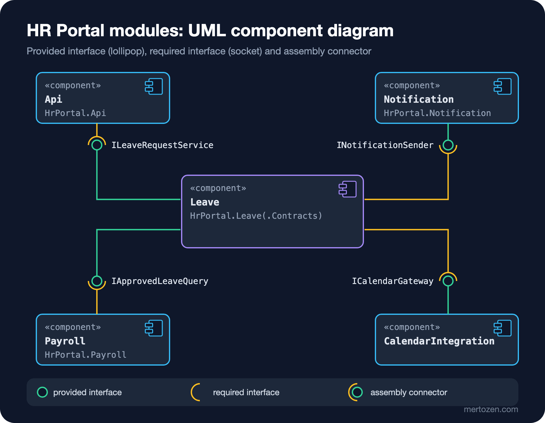
A component is a rectangle marked with the «component» keyword or with the small component icon (a box with two tabs) in the top right corner; using both is fine too. A provided interface is drawn as a full circle at the end of a line coming out of the component, the lollipop (ball): "I implement this contract". A required interface is drawn as a half circle, the socket: "I need this contract to work". When one component's socket holds another's lollipop, the link is called an assembly connector. Each of the four links in the figure shows where one module's need is met by another module.
You can draw the same information more formally: draw the interface as a class box with the «interface» keyword and connect the provided side with a realization (a dashed arrow with a hollow triangle) and the required side with a «use» dependency (a dashed arrow with an open head). That form is useful when you also want to show the interface's operations. Ball-and-socket, on the other hand, makes dependencies between modules readable at a glance. For crowded systems there is also a black-box form: compartments titled «provided interfaces» and «required interfaces» inside the component rectangle, with the interface names listed. It is handy when you want to document the contract without drawing lines.
The reading rule is simple. Lollipop to socket is provider to consumer; socket to lollipop is the direction of the dependency. In the figure Leave offers two lollipops (ILeaveRequestService, IApprovedLeaveQuery) and carries two sockets (INotificationSender, ICalendarGateway). Api and Payroll only consume, Notification and CalendarIntegration only provide. The HTTP (Hypertext Transfer Protocol) call to the Calendar System is hidden inside CalendarIntegration; Leave only sees it as an interface.
Ports, Delegation and Composite Structure
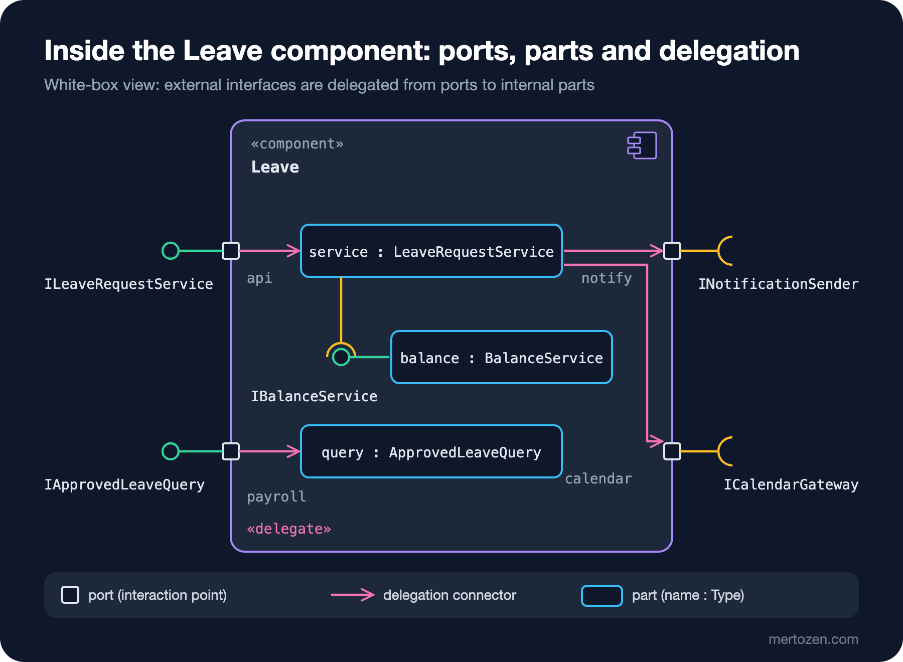
The black-box view serves someone looking from the outside. When you want to open it up, you switch to the white-box view, whose vocabulary comes from UML's composite structure diagram. The small squares sitting on the component's boundary are ports: the component's interaction points with the outside world. Each port can have its own provided and required interfaces, so "the face toward the API (Application Programming Interface)" and "the face toward Payroll" get separate names (api, payroll), and so do the needs (notify, calendar).
The boxes inside are parts, written as name : Type. service : LeaveRequestService stands for a LeaveRequestService instance that exists while the component runs; it is not the class from the class diagram but a role played by an instance of it. The connector drawn from a port to a part is a delegation connector: a call that arrives at the api port from outside is forwarded to service inside. In the other direction, service's need for notifications leaves through the notify port. Many tools show this link with an arrow and a «delegate» label. The ball-and-socket between service and balance inside is also an assembly connector, only this time inside the component.
When should you draw ports? If a component offers different faces to different consumers, or needs the same interface for two different purposes (e.g. two separate calendar systems), ports are how you name those faces. For small modules with a single consumer, lollipops and sockets without ports are enough. The composite structure diagram itself is a more general tool: it shows the runtime internal structure of any class, its parts and the connectors between them. The white-box view of a component is its most common use.
The .NET Counterpart: Module = Component in a Modular Monolith
Every element in the diagram has a counterpart in code. The Leave module consists of two projects: HrPortal.Leave.Contracts, which carries the contracts, and HrPortal.Leave, which carries the implementation. The contracts project contains only interfaces:
namespace HrPortal.Leave.Contracts;

// Provided interface 1: the command face used by the API
public interface ILeaveRequestService
{
    Task ApproveAsync(int leaveRequestId, int approverId, CancellationToken ct = default);
}

// Provided interface 2: the query face read by the Payroll module
public interface IApprovedLeaveQuery
{
    Task<int> GetUnpaidLeaveDaysAsync(int employeeId, int year, int month, CancellationToken ct = default);
}

// Required interface: owned by Leave, implemented by another component
public interface ICalendarGateway
{
    Task AddLeaveAsync(int leaveRequestId, DateOnly start, DateOnly end, CancellationToken ct = default);
}
Putting ICalendarGateway here is a deliberate decision. It is a required interface, but Leave owns it: Leave defines the need, and the calendar integration conforms to it. This is the component-level version of inverting a dependency, which we discussed in the SOLID (Single Responsibility, Open/Closed, Liskov Substitution, Interface Segregation, Dependency Inversion) series post on the Dependency Inversion Principle. INotificationSender, on the other hand, lives in the Notification module's own contracts project, because many modules share it. On the implementation side everything is internal:
internal sealed class LeaveRequestService(
    IBalanceService balance,
    INotificationSender notifications,
    ICalendarGateway calendar) : ILeaveRequestService
{
    public async Task ApproveAsync(int leaveRequestId, int approverId, CancellationToken ct = default)
    {
        if (!balance.HasEnoughBalance(employeeId: 1001, workingDays: 5))
        {
            throw new InvalidOperationException("Insufficient balance.");
        }
        await calendar.AddLeaveAsync(leaveRequestId, new DateOnly(2026, 12, 21), new DateOnly(2026, 12, 25), ct);
        await notifications.SendAsync("ada@hrportal.example", $"Leave request #{leaveRequestId} approved", ct);
    }
}

public static class LeaveModule
{
    // Ports: only two provided interfaces are exposed, the implementations are internal
    public static IServiceCollection AddLeaveModule(this IServiceCollection services)
    {
        services.AddScoped<ILeaveRequestService, LeaveRequestService>();
        services.AddScoped<IApprovedLeaveQuery, ApprovedLeaveQuery>();
        services.AddScoped<IBalanceService, BalanceService>();
        return services;
    }
}
As a reading guide, the mapping is:
| UML element | .NET counterpart |
|---|---|
| Component | Module: one contracts project and one implementation project |
| Provided interface | A public interface in Contracts and the internal class that implements it |
| Required interface | An interface from another module's contracts, requested as a constructor parameter |
| Build-time trace of a required interface | A ProjectReference to the provider's Contracts project, not to its implementation |
| Delegation connector | AddScoped<ILeaveRequestService, LeaveRequestService>(): from the external contract to the internal class |
| Assembly connector | Two modules' registrations satisfying each other in the composition root |
| Port | A contract face split by consumer (a separate interface or a facade) |
The references in HrPortal.Leave.csproj can be read off the diagram as well. Leave's two sockets mean references to two contracts projects, not to implementations:
<ItemGroup>
  <ProjectReference Include="..\HrPortal.Leave.Contracts\HrPortal.Leave.Contracts.csproj" />
  <ProjectReference Include="..\HrPortal.Notification.Contracts\HrPortal.Notification.Contracts.csproj" />
</ItemGroup>
We drew this dependency graph between projects as a package diagram in the series' Object and Package Diagrams post, and how to split projects in the first place is the topic of the SOLID series post Component Principles: Splitting a .NET Solution into Projects. The component diagram sits above both views: it shows contracts, not projects.
Reading DI Registrations as Assembly Connectors
The four assembly connectors in the diagram are set up in a single place in code, the composition root. Every registration in the DI (dependency injection) container is one end of a link:
// Composition root: the assembly connectors are wired here
ServiceCollection services = new();
services.AddLeaveModule();
if (mode != "missing")
{
    services.AddNotificationModule();
}
services.AddCalendarIntegration();
services.AddPayrollModule();
In the sample data Ada has 3 working days of unpaid leave in November 2026, and Payroll reduces her gross salary accordingly, assuming 22 working days a month. When we run it, the Leave module handles the approval and the calendar and notification modules are called through their contracts:
Approve #42 by Grace:
  [Calendar] leave #42 2026-12-21..2026-12-25 added
  [Notification] e-mail to ada@hrportal.example: Leave request #42 approved
Payroll: Ada, 2026-11 gross = 57000
The more interesting part is reading the links back from code. The constructor parameters of each registered class are its required interfaces, and the registration that satisfies a parameter is the other end of the assembly connector. A few lines of reflection print them:
static void PrintWiring(IServiceCollection services)
{
    // Every constructor parameter is a required interface; the registration that satisfies it is an assembly connector
    foreach (ServiceDescriptor d in services.Where(d => d.ImplementationType is not null))
    {
        Type impl = d.ImplementationType!;
        ConstructorInfo ctor = impl.GetConstructors(BindingFlags.Public | BindingFlags.Instance).Single();
        foreach (ParameterInfo p in ctor.GetParameters())
        {
            ServiceDescriptor? provider = services.LastOrDefault(s => s.ServiceType == p.ParameterType);
            string by = provider?.ImplementationType is { } t ? $"{t.Assembly.GetName().Name}.{t.Name}" : "MISSING";
            Console.WriteLine($"{impl.Assembly.GetName().Name,-22} {impl.Name,-20} requires {p.ParameterType.Name,-20} <- {by}");
        }
    }
}
HrPortal.Leave LeaveRequestService requires IBalanceService <- HrPortal.Leave.BalanceService
HrPortal.Leave LeaveRequestService requires INotificationSender <- HrPortal.Notification.EmailNotificationSender
HrPortal.Leave LeaveRequestService requires ICalendarGateway <- HrPortal.CalendarIntegration.CorporateCalendarGateway
HrPortal.Payroll PayrollCalculator requires IApprovedLeaveQuery <- HrPortal.Leave.ApprovedLeaveQueryThree of the four lines are the links between modules in the figure, one (IBalanceService) is the internal link from the white-box view. The assembly name tells you whether both ends live in the same module or not. Comparing this output with the diagram is a cheap answer to "is the diagram still correct?".
And what if a socket is left empty? Building the container with ValidateOnBuild on but without registering the Notification module gives this real error:
Error while validating the service descriptor 'ServiceType: HrPortal.Leave.Contracts.ILeaveRequestService Lifetime: Scoped ImplementationType: HrPortal.Leave.LeaveRequestService': Unable to resolve service for type 'HrPortal.Notification.Contracts.INotificationSender' while attempting to activate 'HrPortal.Leave.LeaveRequestService'.In diagram terms: no lollipop plugs into Leave's INotificationSender socket. Without ValidateOnBuild this error would surface on the first approval request, in production. In ASP.NET Core this validation is on by default in the Development environment. Lifetimes and validation are covered in the ASP.NET Core Web API series post Dependency Injection in ASP.NET Core: Lifetimes and the Captive Dependency Trap.
Diagrams as Code: A Component Diagram in PlantUML
Below is the PlantUML counterpart of the black-box view in the figure, rendered with PlantUML 1.2026.9. -( draws the socket, a plain line draws the lollipop:
@startuml hr-portal-components
title HR Portal modules (UML component diagram)
skinparam componentStyle uml2

component "HrPortal.Api" as Api
component "Leave" as Leave
component "Payroll" as Payroll
component "Notification" as Notification
component "CalendarIntegration" as Calendar

interface ILeaveRequestService
interface IApprovedLeaveQuery
interface INotificationSender
interface ICalendarGateway

Leave -up- ILeaveRequestService
Leave -down- IApprovedLeaveQuery
Notification -left- INotificationSender
Calendar -left- ICalendarGateway

Api -down-( ILeaveRequestService
Payroll -up-( IApprovedLeaveQuery
Leave -right-( INotificationSender
Leave -right-( ICalendarGateway
@enduml
The automatic layout is not as tidy as the hand-drawn figure, but the information is the same and the file can change in the repo together with the code. Mermaid 12.3.0, the version current at the time of writing, has no UML component diagram type, which is why PlantUML fits component and deployment diagrams better. We compare the tools in the series' Mermaid and Structurizr DSL (domain-specific language) post.
How It Differs from a C4 Component Diagram
The similar name is confusing. The C4 (Context, Containers, Components, Code: Simon Brown's four-level approach to architecture diagrams) model also says "component", but with a narrower meaning: a grouping of related functionality behind a well-defined interface, inside a container, i.e. inside a separately running application or data store. According to C4 a component is not deployed on its own and runs in the container's process. Our Leave, Payroll and Notification modules fit that definition exactly.
The difference is in notation and purpose. A C4 component diagram has no ports, lollipops or sockets; it has boxes and one-way arrows labeled with "what for, with which technology". Its audience is developers and architects who want to grasp the architecture quickly. A UML component diagram pins down the contract: who provides which interface, who requires it, through which port. A practical rule: C4 when explaining the architecture, UML when two teams need to agree on a module boundary. They do not exclude each other: you draw a container's components in C4 and detail a critical boundary with a UML component diagram. We cover all of C4 and its notation rules two posts from now, in the C4 Model post.
Common Pitfalls
Turning every class into a component. BalanceService is not a component but an internal part of Leave. A component is an independently replaceable unit wired by contracts. If your diagram has forty boxes, you are probably drawing a class diagram with component notation.
Pointing arrows at implementations. An arrow from Payroll to ApprovedLeaveQuery inside Leave is the diagram version of the shortcut from the opening. A dependency always goes to an interface. In code, internal and a separate contracts project enforce that; in the diagram, only discipline does.
Leaving a socket dangling. A component with a required interface that is connected to nothing points to either a missing module or a DI registration that will blow up at runtime. When drawing, ask "who provides this?" for every socket. In code, ValidateOnBuild asks the same question for you.
Confusing components with deployment. If your component diagram has boxes like "API server" or "database machine", you are no longer drawing logical structure but physical topology. That belongs in a deployment diagram.
Not tying the diagram to code. If the links between modules are not verified by an output like the one above or by an architecture test (e.g. NetArchTest rules), the two drift apart at the first refactoring.
A Small Experiment
★☆☆ Add a new internal service called IWorkingDayCalculator inside HrPortal.Leave and give it to LeaveRequestService as a constructor parameter. How many lines does the wiring output have now? Which part and which connector should be added to the white-box figure?
★★☆ Instead of querying through IApprovedLeaveQuery, let the Payroll module listen to the LeaveRequestApproved integration event published by the Leave module. How does the component diagram change: do lollipop and socket swap direction, or does an event bus component appear in between? Compare the coupling of the two designs.
★★★ Write an architecture test that verifies the HrPortal.Payroll assembly depends only on HrPortal.Leave.Contracts and not on HrPortal.Leave. Then put a short explanation into the test name that maps the rule to a socket in the component diagram.
The component diagram told us what depends on what at the logical level. In the next post we look at where these modules run: with a deployment diagram we draw nodes, execution environments, artifacts and the «manifest» relationship, using the HR Portal's development environment set up with docker compose and its production topology on Azure.