

The C4 Model: Context, Container, Component, Code and Notation Rules
The C4 model describes a software system as zooming maps at the Context, Container, Component and Code levels, each for a different reader; the first two levels are enough for most teams, and a C4 container is not a Docker container but a running application or data store. In this post we draw the HR Portal's Context, Container and Component diagrams following the notation checklist, write them as C4-PlantUML and show how to use C4 together with UML.
Version note: The diagrams in this post use C4 (Context, Containers, Components, Code) model and UML (Unified Modeling Language) 2.5.1 notation; the PlantUML example was rendered with PlantUML 1.2026.9 and C4-PlantUML 2.14.0, the Mermaid example with Mermaid 12.3.0; the series' code base is .NET 10.
Guess First: How Many Containers Does the HR Portal Have?
A developer who just joined the team asks a simple question: "How many containers does the HR (human resources) Portal consist of?" Three people give three answers. Ada, a developer, points at the compose file from the previous post:
sqlserver
servicebus
worker
redis
api
"Five." Linus from ops says "in production there are two container apps, the API (Application Programming Interface) and the worker". Grace, the architect, counts six, and her list includes the Angular application, which is not in the compose file at all. Which one is right? Is the question wrong, or does the word "container" mean three different things to three people? Before reading on, guess what the sixth item on Grace's list might be.
What Is C4? Four Levels and Their Audiences
The C4 model is an approach proposed by Simon Brown for describing software architecture at four levels that zoom into each other. Its sources are the c4model.com site and The C4 Model book published by O'Reilly in 2026. The idea comes from maps: first you show the country, then the city, then the neighborhood and finally the street; each map zooms into the previous one, and each has a different reader. C4 is not a notation but a set of abstractions: it defines what each box means and leaves its shape and color to you.
| Level | Scope | Audience | Recommendation |
|---|---|---|---|
| 1. System Context | A single software system and its surroundings | Everyone, technical or not | For every team |
| 2. Container | The running applications and data stores inside a system | Architects, developers, ops | For every team |
| 3. Component | The inside of a single container | Architects and developers | If it adds value; generate it for long-lived documentation |
| 4. Code | The classes of a single component | Developers | Not recommended; generate it with tooling if needed |
The last column carries C4's most overlooked message: you do not have to draw all four levels. c4model.com states plainly that Context and Container diagrams are enough for most teams. The Component level should only be drawn if it really helps, and the Code level should almost never be drawn by hand.
A "Container" Is Not a Docker Container
This is the source of the confusion in the opening. In C4 a container is a runtime boundary around code being executed or data being stored: a separately deployed application or data store that must be running for the system to work. A server-side web application, an SPA (single-page application) running in the browser, a console application, a serverless function, a database schema or a blob store are all containers. c4model.com deliberately opens that page with a "Not Docker!" warning. The name is a generic word chosen before Docker.
With this definition, Grace's six containers are: the Angular SPA, the API, the worker, the database, the cache and the leave-events topic. The sixth item is the Angular application. It does not run in Docker, but it is a separate application running in the user's browser. The sqlserver, redis and servicebus entries in Ada's list show which Docker containers these containers run in during development, i.e. deployment information. Linus's two container apps are the same thing for production. All three answers are right for their own question; what C4 provides is names that put those three questions into separate diagrams.
There are two more edge cases. A DLL (dynamic-link library) or a NuGet package is not a container, because it does not run on its own; it organizes code. That is why HrPortal.Leave.dll from the previous posts is at most the physical counterpart of a component in C4. For message queues and topics C4 suggests two ways: draw each queue or topic as its own container (a data store), or hide the queue and write "via leave-events" on the relationship label. The broker itself (the Service Bus namespace) is not a container. We drew leave-events as an explicit container, because seeing that the link between API and worker goes through a topic matters architecturally.
Level 1: System Context
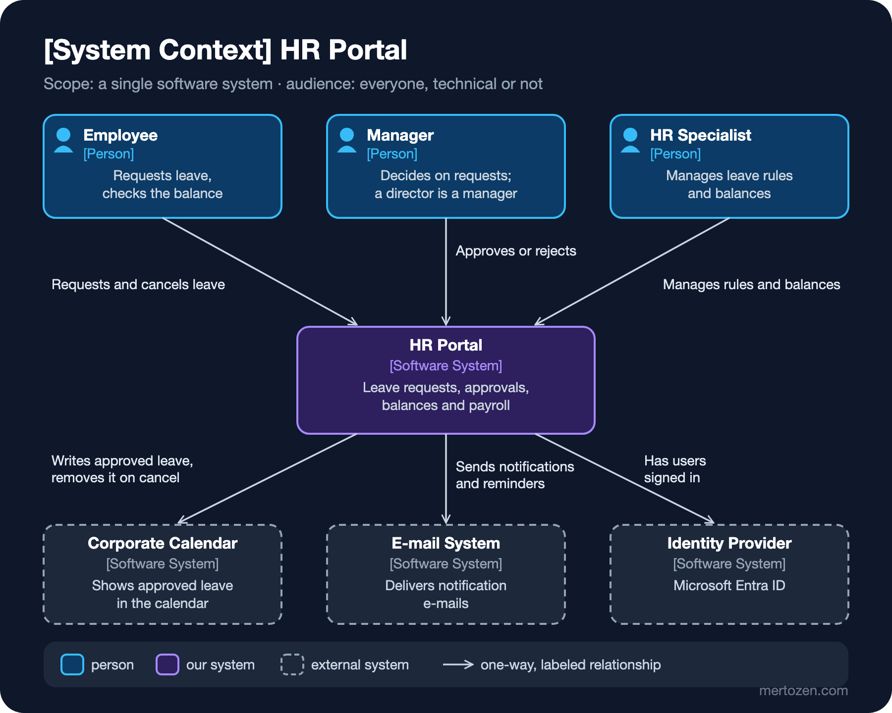
At the center of the context diagram there is a single box: the HR Portal. Around it are the people who use it and the external systems it talks to. No technologies, protocols or internal structure; the HR director and the information security team must both be able to read this diagram. The people are the same as the actors in the use case diagram: Employee, Manager (a director is a manager too) and HR Specialist. The external systems are the corporate calendar, the e-mail system and the identity provider.
The real job of this diagram is to draw the boundary. Payroll is inside our system, the calendar is not. Authentication is someone else's responsibility, and so is e-mail delivery. In a security review or an integration meeting the first question is "where does your system end?", and this single page answers it. Notice that every arrow is one-way and says what it is for; there are no vague one-word labels like "uses".
Level 2: Container
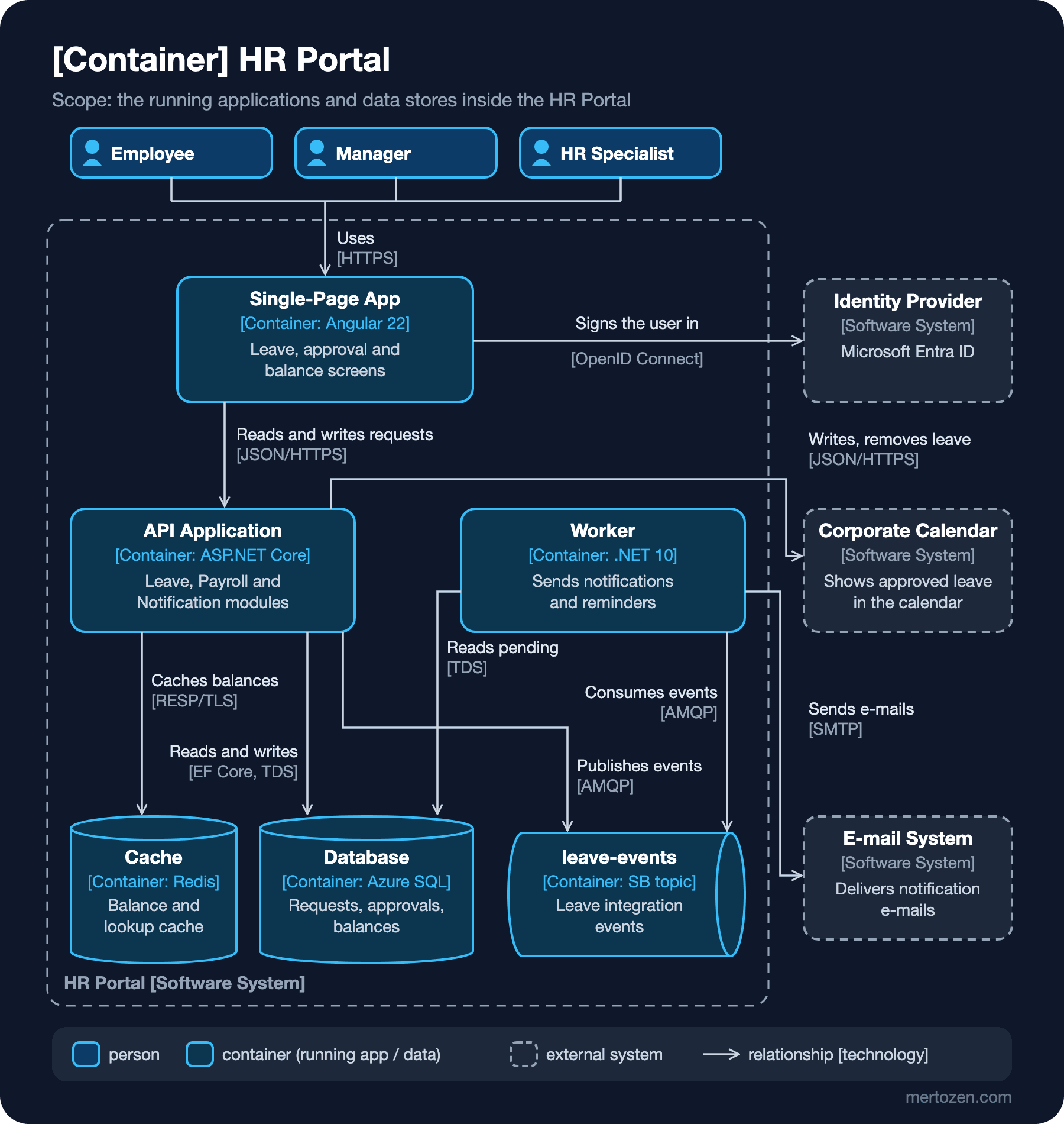
The container diagram opens the HR Portal box. The six containers inside the dashed boundary are the answer to the opening question. Every box has a name, a type, a technology and a one-sentence responsibility. Every arrow is one-way and carries its technology in square brackets: [JSON/HTTPS], [EF Core, TDS], [AMQP]. Because relationships between containers are usually inter-process communication, the technology label is considered mandatory here.
What is missing from the diagram is missing on purpose. There are no replica counts, Azure regions, Front Door or port numbers. These change from environment to environment, and they live in the deployment diagram from the previous post. The container diagram stays the same in development and in production; only where the containers run changes. The diagrams-as-code counterpart of the same model is below, written with C4-PlantUML 2.14.0:
@startuml hr-portal-containers
!include <C4/C4_Container>

title Container diagram for HR Portal

Person(employee, "Employee", "Requests leave and checks the balance")
Person(manager, "Manager", "Approves or rejects leave requests; a director is a manager")
Person(hr, "HR Specialist", "Manages leave types, holidays and balances")
System_Ext(calendar, "Corporate Calendar System", "Shows approved leave in the company calendar")
System_Ext(smtp, "E-mail System", "Delivers notification e-mails")
System_Ext(idp, "Identity Provider", "Microsoft Entra ID")

System_Boundary(hrportal, "HR Portal") {
    Container(spa, "Single-Page Application", "Angular 22", "Leave request, approval and balance screens")
    Container(api, "API Application", "ASP.NET Core, .NET 10", "Leave, Payroll and Notification modules")
    Container(worker, "Worker", ".NET 10 Worker Service", "Sends notifications and approval reminders")
    ContainerDb(db, "Database", "Azure SQL Database", "Leave requests, approvals, balances")
    ContainerDb(cache, "Cache", "Azure Managed Redis", "Balances and lookup data")
    ContainerQueue(topic, "leave-events", "Azure Service Bus topic", "Leave request integration events")
}

Rel(employee, spa, "Creates and cancels leave requests", "HTTPS")
Rel(manager, spa, "Approves or rejects requests", "HTTPS")
Rel(hr, spa, "Maintains leave rules and balances", "HTTPS")
Rel(spa, idp, "Signs the user in", "OpenID Connect")
Rel(spa, api, "Reads and writes leave data", "JSON/HTTPS")
Rel(api, db, "Reads and writes", "EF Core, TDS")
Rel(api, cache, "Caches balances", "RESP/TLS")
Rel(api, topic, "Publishes LeaveRequestApproved etc.", "AMQP")
Rel(api, calendar, "Adds and removes leave entries", "JSON/HTTPS")
Rel(worker, topic, "Consumes events from", "AMQP")
Rel(worker, db, "Reads pending requests", "TDS")
Rel(worker, smtp, "Sends e-mails via", "SMTP")

SHOW_LEGEND()
@enduml
The Container, ContainerDb and ContainerQueue macros choose the shape, the fourth argument of Rel is the technology label, and SHOW_LEGEND() generates the legend the checklist asks for. Mermaid 12.3.0 also supports C4 diagrams, with a syntax deliberately modeled on C4-PlantUML:
C4Context
    title System Context diagram for HR Portal
    Person(employee, "Employee", "Requests leave and checks the balance")
    Person(manager, "Manager", "Approves or rejects leave requests")
    System(hrportal, "HR Portal", "Leave requests, approvals, balances and payroll")
    System_Ext(calendar, "Corporate Calendar System", "Shows approved leave")
    Rel(employee, hrportal, "Requests and cancels leave")
    Rel(manager, hrportal, "Approves or rejects requests")
    Rel(hrportal, calendar, "Writes approved leave, removes it on cancel", "JSON/HTTPS")
This text renders with Mermaid 12.3.0, but two limits show up right away. According to the Mermaid documentation the layout is not automated and boxes are placed in statement order; in our attempt the label of the calendar relationship landed on top of the box. There is no legend support yet either. It is fine for a quick sketch, but for a document that follows the notation checklist, C4-PlantUML or Structurizr fits better. We compare the three tools in the series' Mermaid and Structurizr DSL (domain-specific language) post.
Level 3: Component and Level 4: Code
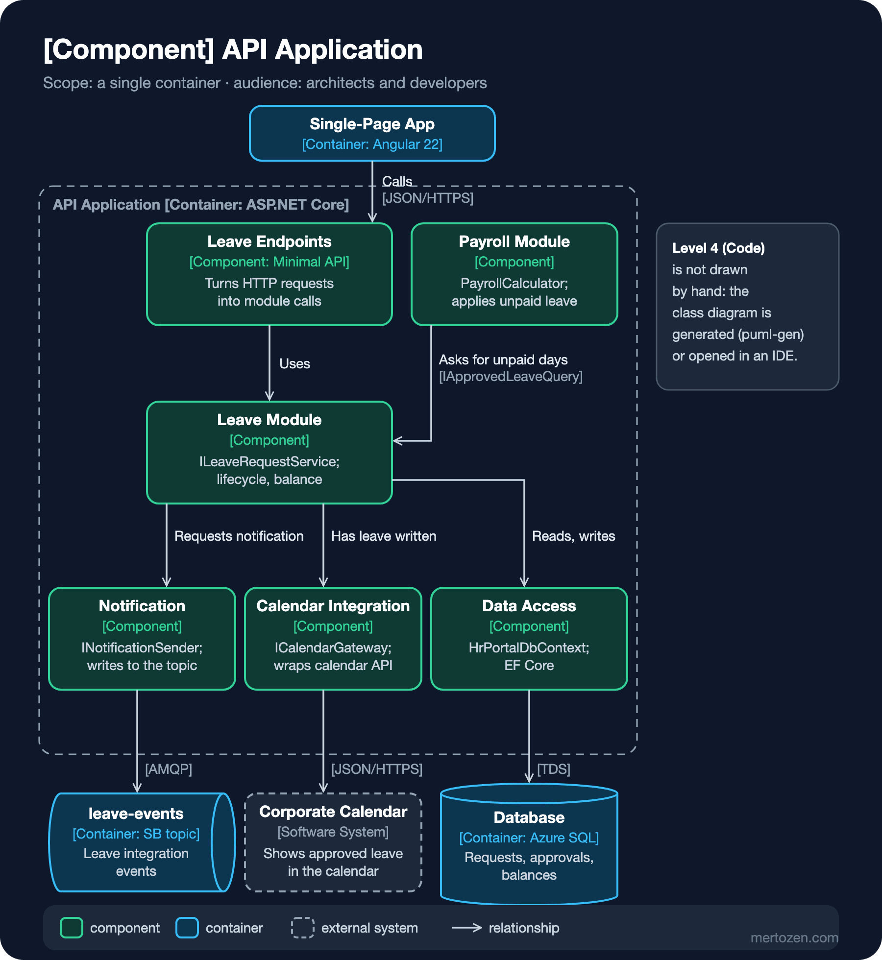
A component diagram opens a single container; here, the API Application. In C4 a component is a grouping of related functionality behind a well-defined interface. It is not deployed separately and runs in the container's process. For C#, the simplest mental model is an interface and the classes that implement it. Our components are the same as the modules from the Component Diagrams post: Leave, Payroll, Notification and Calendar Integration. Added to them are the endpoints that handle HTTP (Hypertext Transfer Protocol) requests and data access. Each box names an interface or class, so the path from the diagram to the code is a single step.
This is where the difference from the UML component diagram becomes concrete. We drew the same Leave and Payroll relationship in UML with lollipops, sockets and ports; in C4 there is a single labeled arrow: "Asks for unpaid days [IApprovedLeaveQuery]". The C4 diagram tells the reader "what exists and what talks to what"; UML pins down the direction and ownership of the contract.
The fourth level, Code, is the class diagram of a component. c4model.com explicitly does not recommend it. If needed, an IDE (integrated development environment) or a modeling tool should generate it. A hand-drawn class diagram goes stale at the first refactoring. We covered generating diagrams from code in the series' From Class Diagram to Code and Back: Domain Model, Design Model and puml-gen post. What C4's fourth level needs is simply linking that post's puml-gen output to the relevant component.
The Notation Checklist
C4 does not impose shapes or colors, but it requires a diagram to explain itself. The items of the notation checklist on c4model.com, and how our diagrams meet them:
- The title states the diagram's type and scope, like
[Container] HR Portal. - Every diagram has a legend explaining shapes, colors, line styles and arrowheads, even when it is drawn in UML.
- Business and technical acronyms are understandable to every reader or explained in the legend.
- Every element states its type (
[Person],[Software System],[Container],[Component]) and carries a short responsibility sentence. - The technology of every container and component is stated.
- Every line is one-way and its label matches its direction; it says the purpose instead of vague single words like "uses".
- Relationships between containers carry a technology or protocol label; colors are chosen with color blindness and black-and-white printing in mind.
The last item required a decision in our figures too: we separated people, systems and containers not only by color but also by border style. External systems have dashed borders, people have a person icon. That way the distinction survives a black-and-white printout or a reader who cannot tell the colors apart.
Supplementary Diagrams: System Landscape, Dynamic and Deployment
Next to the four core levels, C4 defines three supplementary diagrams. A system landscape shows all of a company's software systems and the relationships between them in one picture. The HR Portal, the accounting system that pays salaries, the corporate calendar and the identity provider appear on the same map. When several teams run several systems in an organization, this is the first diagram that sits above the context diagrams.
A dynamic diagram shows, with numbered arrows, how the elements of a static diagram collaborate in a particular scenario; for example the "leave approved" flow: the SPA calls the API, the API writes to the database and publishes an event to the topic, the worker picks up the event and sends an e-mail. It is a lighter sibling of the UML sequence diagram. If you need to show message kinds, fragments and error paths, you go back to the series' Sequence Diagram posts. The deployment diagram, finally, is derived from the UML deployment diagram we saw in the previous post. Deployment nodes are nested and container instances are placed inside them, one diagram per environment.
Using UML and C4 Together
In this series we use the two as layers, not rivals. C4 provides the skeleton: the Context and Container diagrams are the first two pages of the architecture document and orient someone who does not know the system within ten minutes. UML provides the detail at the critical points of the skeleton. The leave request lifecycle is told with a state machine diagram, a module boundary with a UML component diagram, the error paths of the approval flow with a sequence diagram, and the production topology with a deployment diagram. A practical rule: if the reader asks "what exists and what does it talk to?", use C4; if they ask "how exactly does it behave, or which contract binds it?", use UML.
C4 also has a role in long-lived documentation. When an architectural decision is made, for example "Payroll should listen to events instead of querying the Leave module", these diagrams show which containers and components the decision affects. Writing the decision itself as an ADR (Architecture Decision Record) and attaching the diagram to it is something we will do in the upcoming Architecture Decisions series. That series will not explain the C4 notation again; it will build on this post.
Common Pitfalls
The unlabeled box-and-arrow diagram. The classic whiteboard picture: six boxes, ten arrows, not a single arrow says what it carries and no box names its technology. Everyone who reads it understands something different. Almost the entire checklist was written against this one pitfall.
Mistaking a container for a Docker container. Drawing the sqlserver, redis and servicebus Docker containers on the container diagram and forgetting the Angular application means drawing a deployment diagram at the wrong level. First ask "what must be running for the system to work?", and leave "where does it run?" to the deployment diagram.
Drawing the Code level by hand. Hand-drawn class diagrams for every component are the most expensive documentation to maintain and the fastest to go stale. Generate them if you need them; otherwise do not draw them.
Mixing levels in one diagram. Putting a database on the context diagram or class names on the container diagram breaks the map in the reader's head. Each diagram should stay at one scope and one level of abstraction. If you want to zoom in, draw the next level's diagram.
Two-way and vague arrows. "API ↔ Database: uses" says nothing. "The API reads and writes requests [EF Core, TDS]" states the direction, the purpose and the technology.
A Small Experiment
★☆☆ Assume the HR Portal sends a monthly unpaid-leave report to an Accounting System that pays the salaries. What gets added to the context diagram? Write the label so that it follows the checklist.
★★☆ Draw a C4 dynamic diagram for the "leave approval" scenario: SPA, API, Database, leave-events, Worker and E-mail System with numbered steps. Then compare it with the sequence diagram of the same scenario in this series: what does the dynamic diagram not show?
★★★ Put the C4-PlantUML source of the container diagram into the repo and write an alternative version that hides the leave-events topic: a single relationship between API and Worker labeled "via leave-events". Show both versions to a teammate and discuss which one describes the architecture more accurately. Which of C4's "explicit" and "implicit" queue options did you choose, and why?
So far we have looked at behavior and architecture diagrams. In the next post we go down to the data itself: with ER (Entity-Relationship) diagrams we look at Chen and Crow's Foot notation, reading cardinality and optionality, and the step from the Leave module's class diagram to tables.