

From Class Diagram to Code and Back: Domain Model, Design Model and puml-gen
A domain model shows business concepts without types or operations, while a design class diagram shows the C#-level design decisions for the same case; the first is drawn by hand, slices of the second become code, and diagrams generated from code with tools like puml-gen are for observation and drift checks only. The post takes the HR Portal leave module from diagram to EF Core configuration and DDL, then back to PlantUML with puml-gen.
Version note: The diagrams in this post use UML (Unified Modeling Language) 2.5.1 notation; the C# examples were tested with .NET 10 and Entity Framework Core (EF Core) 10, and the generated diagrams with PlantUmlClassDiagramGenerator 1.4.0 and PlantUML 1.2026.9.
Guess First: Which Diagram Do You Send to the New Hire?
A new developer joined the HR Portal team and asked on day one: "how does the leave module work, is there a diagram?" Someone on the team spent five minutes on it: ran a class diagram generator at the root of the solution, converted the result to PNG (Portable Network Graphics) and sent it over.
dotnet tool install --local PlantUmlClassDiagramGenerator
dotnet puml-gen src docs/all -dir -createAssociation -allInOne
docker run --rm -v "$PWD":/data plantuml/plantuml -tpng /data/docs/all/include.puml
The solution has four projects: HrPortal.Leave.Domain, HrPortal.Leave.Application, HrPortal.Leave.Infrastructure and HrPortal.Api. How many boxes end up in the generated diagram, and how wide is the image? More importantly: can the new colleague look at it and answer "where does LeaveRequestService check the balance?"
The Answer: 56 Boxes, 14,166 Pixels and Invisible Dependencies
The real run: PlantUML's SVG (Scalable Vector Graphics) output is 14,166 × 788 pixels, with 56 boxes and 54 arrows. The PNG was cut off at 4096 pixels, because by default PlantUML does not draw past that limit (PLANTUML_LIMIT_SIZE). Two thirds of the picture simply are not there. In the part that remains, framework types such as DateTimeOffset and DateOnly sit in their own class boxes, and the first run also produced 12 empty .puml files for the generated sources under obj.
The real question stays unanswered. There is not a single arrow from LeaveRequestService to IBalanceService. The reason is simple: the service uses a primary constructor and the tool does not see primary constructor parameters. Write the same dependency with a classic constructor and a private readonly field, and the arrow appears:
public sealed class PrimaryCtorService(IBalanceService balances)
{
    public bool Check() => balances is not null;
}

public sealed class FieldService
{
    private readonly IBalanceService balances;

    public FieldService(IBalanceService balances) => this.balances = balances;

    public bool Check() => balances is not null;
}
class PrimaryCtorService <<sealed>> {
+ Check() : bool
}
class FieldService <<sealed>> {
+ FieldService(balances:IBalanceService)
+ Check() : bool
}
FieldService --> "balances" IBalanceServiceThat is the topic of this post: moving between diagram and code in both directions. First we look at the same case drawn at two different levels (domain model and design class diagram), then we go from the diagram to C# and EF Core code (forward engineering), and finally from code back to a diagram (reverse engineering). Which diagrams to keep by hand and which to generate will answer itself along the way.
Two Levels of the Same Case: Domain Model and Design Class Diagram
The previous two posts of the series covered class diagram notation: attributes, operations, visibility, multiplicity and relationship types. But the same notation can draw two very different things. Craig Larman names them separately in Applying UML and Patterns (3rd edition, 2004): a domain model is a visual representation of the concepts in the problem domain; it shows things from the business world, not software classes. A design class diagram (DCD) shows the actual software classes with their types, operations and who knows whom. Martin Fowler describes a similar split in UML Distilled as perspectives: the conceptual perspective and the software perspective. The same box says different things in each.
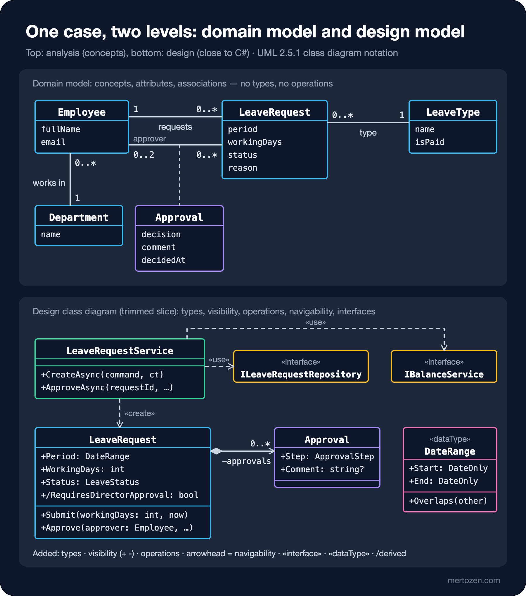
The domain model at the top has Employee, LeaveRequest, LeaveType, Department and Approval. Attributes have no types, there is no operation compartment and no arrowheads. Sentences like "an employee opens zero or more leave requests" and "a request is decided by at most two approvers" are read from the multiplicities. Approval is an association class: it says the "approver" relationship between an employee and a request itself carries a decision, a comment and a date. You can discuss this diagram at the same table with the HR directorate; there is not a single word in it they do not know.
The design class diagram at the bottom shows the design decisions for the same case. There is a class called LeaveRequestService; no such concept exists in the business world, we invented it while distributing responsibilities. There are two «interface» boxes: ILeaveRequestRepository and IBalanceService, which the service depends on without knowing their implementations. Dependencies are dashed lines with open arrowheads, marked with the «use» and «create» keywords. period is now Period: DateRange, and DateRange is marked «dataType» because it has no identity and is compared by value. The relationship between LeaveRequest and Approval became a composition, and the arrowhead shows navigability: the request knows its approvals, and the Approvals collection is its counterpart in code.
Domain Model: What Goes In, What Stays Out?
The domain model has one job: capture the concepts and their relationships correctly. From the requirement text (R1–R12 in the second post of the series), nouns came out as candidate concepts and verbs as candidate associations; the domain model is the cleaned-up version. What goes in: concept classes, attributes that matter to the business, associations and multiplicities, and generalization or association classes where needed.
What stays out is more instructive. No operations, because the answer to "who approves" is not a method yet but a decision about distributing responsibility. No visibility, because concepts have nothing private. No foreign key attributes such as Id or EmployeeId; the relationship is already shown by the association, and a foreign key is a database decision. No interfaces, repositories, DbContexts or controllers. And no navigability arrows: "does the request know the employee, or does the employee know the requests?" is a design question, not an analysis question.
You have to draw this diagram by hand, because it has no counterpart in code. The code has Employee.FullName, but "a request goes through at most two approvers" is not written in any property; it is spread across an if inside the Approve method. With a diagrams-as-code approach it can be kept in PlantUML like this:
@startuml leave-domain-model
hide circle
hide empty methods

class Employee {
  fullName
  email
}
class Department {
  name
}
class LeaveRequest {
  period
  workingDays
  status
  reason
}
class LeaveType {
  name
  isPaid
}
class Approval {
  decision
  comment
  decidedAt
}

Employee "0..*" -- "1" Department : works in
Employee "1" -- "0..*" LeaveRequest : requests
Employee "0..2 approver" -- "0..*" LeaveRequest
(Employee, LeaveRequest) .. Approval
LeaveRequest "0..*" -- "1" LeaveType : type
@enduml
The (Employee, LeaveRequest) .. Approval line is PlantUML's association class syntax; when rendered, the Approval box is attached with a dashed line to the association line between the two classes. This file rendered without errors with PlantUML 1.2026.9. PlantUML itself is covered in detail in the upcoming Diagrams as Code with PlantUML post of this series.
Design Class Diagram: Where Do the Decisions Come From?
Every element added on the way from domain model to design model is a record of a decision. Listing those decisions is the shortest way to understand why the diagram looks the way it does:
- Responsibility: who runs the "create and submit a request" flow? An application service (
LeaveRequestService). Business rules live in the methods ofLeaveRequestitself (Submit,Approve,Cancel). - Types:
periodis not two separateDateOnlyvalues but aDateRangewith anOverlapsbehavior;statusis an enum;LeaveTypeis not an enum but an entity HR can define (R12). - Navigability:
LeaveRequestknows its approvals andApprovalknows which request it belongs to.Employeedoes not know its requests; we find an employee's requests with a query. - Dependency direction: the service depends on interfaces, not on infrastructure. The implementations live in
HrPortal.Leave.Infrastructure. - Derived attribute:
/RequiresDirectorApprovalis not stored, it is computed fromWorkingDays > 3(R7).
A design class diagram does not have to show the whole system, and it is better if it does not. The bottom card in the figure is a slice: the classes that realize the "Request Leave" use case. Larman also treats the DCD as something that grows piece by piece together with the design of use cases (interaction diagrams). In the upcoming sequence diagram post we will draw the messages inside this slice.
Forward Engineering: From Diagram to C# and EF Core
Every element of the design class diagram has a counterpart in C# and EF Core. First LeaveRequest:
public class LeaveRequest
{
    public const int DirectorApprovalThreshold = 3;

    private readonly List<Approval> approvals = [];

    private LeaveRequest() { } // for EF Core

    public LeaveRequest(Employee employee, LeaveType leaveType, DateRange period, string? reason, DateTimeOffset now)
    {
        Employee = employee;
        EmployeeId = employee.Id;
        LeaveType = leaveType;
        LeaveTypeId = leaveType.Id;
        Period = period;
        Reason = reason;
        Status = LeaveStatus.Draft;
        CreatedAt = now;
    }

    public int Id { get; private set; }
    public int EmployeeId { get; private set; }
    public Employee Employee { get; private set; } = null!;
    public int LeaveTypeId { get; private set; }
    public LeaveType LeaveType { get; private set; } = null!;
    public DateRange Period { get; private set; }
    public int WorkingDays { get; private set; }
    public string? Reason { get; private set; }
    public LeaveStatus Status { get; private set; }
    public DateTimeOffset CreatedAt { get; private set; }
    public LeaveAttachment? Attachment { get; private set; }
    public IReadOnlyList<Approval> Approvals => approvals;

    public bool RequiresDirectorApproval => WorkingDays > DirectorApprovalThreshold;

    public void Submit(int workingDays, DateTimeOffset now) { /* ... */ }
    public void Approve(Employee approver, string? comment, DateTimeOffset now) { /* ... */ }
}

public readonly record struct DateRange
{
    public DateRange(DateOnly start, DateOnly end)
    {
        if (end < start)
            throw new ArgumentException("End date cannot be before start date.", nameof(end));
        Start = start;
        End = end;
    }

    public DateOnly Start { get; }
    public DateOnly End { get; }

    public bool Overlaps(DateRange other) => Start <= other.End && other.Start <= End;
}
The code also contains things the diagram does not: the EmployeeId and LeaveTypeId foreign keys, the private constructor EF Core needs, nullable warnings silenced with = null!. These are implementation details, not design decisions; we did not put them in the design class diagram and we should not. The mapping between notation and EF Core lives in the configuration:
internal sealed class LeaveRequestConfiguration : IEntityTypeConfiguration<LeaveRequest>
{
    public void Configure(EntityTypeBuilder<LeaveRequest> b)
    {
        // «dataType» DateRange: no identity, becomes two columns in the table
        b.ComplexProperty(r => r.Period, p =>
        {
            p.Property(x => x.Start).HasColumnName("StartDate");
            p.Property(x => x.End).HasColumnName("EndDate");
        });
        b.Property(r => r.Status).HasConversion<string>().HasMaxLength(32);
        b.Property(r => r.Reason).HasMaxLength(500);
        // composition [0..1]: owned type, same table
        b.OwnsOne(r => r.Attachment, a =>
        {
            a.Property(x => x.FileName).HasMaxLength(260);
            a.Property(x => x.ContentType).HasMaxLength(100);
            a.Property(x => x.StoragePath).HasMaxLength(400);
        });
        // composition [0..*]: approvals die with the parent
        b.HasMany(r => r.Approvals).WithOne(a => a.LeaveRequest)
            .HasForeignKey(a => a.LeaveRequestId).OnDelete(DeleteBehavior.Cascade);
        b.Navigation(r => r.Approvals).HasField("approvals");
        // derived attribute: no column in the database
        b.Ignore(r => r.RequiresDirectorApproval);
    }
}
Putting the diagram-to-code mapping in a table makes the list of decisions explicit:
| In the diagram | C# | EF Core and database |
|---|---|---|
| Class, attribute | class, property | entity, column |
«dataType» (DateRange) | readonly record struct | ComplexProperty, columns in the same table |
Composition [0..1] (Attachment) | nullable property | OwnsOne, nullable columns in the same table |
Composition [0..*] (Approvals) | private List + IReadOnlyList | foreign key + ON DELETE CASCADE |
Association [1] (LeaveType) | navigation property + foreign key property | foreign key, NO ACTION |
Derived /RequiresDirectorApproval | expression-bodied property | Ignore, no column |
| Enumeration (LeaveStatus) | enum | HasConversion<string>() |
The last step is the DDL (Data Definition Language) EF Core generates from this model, that is, the SQL (Structured Query Language) script that creates the tables. Database.GenerateCreateScript() produced this for SQL Server (shortened):
CREATE TABLE [LeaveRequests] (
    [Id] int NOT NULL IDENTITY,
    [EmployeeId] int NOT NULL,
    [LeaveTypeId] int NOT NULL,
    [WorkingDays] int NOT NULL,
    [Reason] nvarchar(500) NULL,
    [Status] nvarchar(32) NOT NULL,
    [CreatedAt] datetimeoffset NOT NULL,
    [SubmittedAt] datetimeoffset NULL,
    [Attachment_FileName] nvarchar(260) NULL,
    [Attachment_ContentType] nvarchar(100) NULL,
    [Attachment_StoragePath] nvarchar(400) NULL,
    [EndDate] date NOT NULL,
    [StartDate] date NOT NULL,
    CONSTRAINT [PK_LeaveRequests] PRIMARY KEY ([Id]),
    CONSTRAINT [FK_LeaveRequests_Employees_EmployeeId] FOREIGN KEY ([EmployeeId]) REFERENCES [Employees] ([Id]) ON DELETE NO ACTION,
    CONSTRAINT [FK_LeaveRequests_LeaveTypes_LeaveTypeId] FOREIGN KEY ([LeaveTypeId]) REFERENCES [LeaveTypes] ([Id]) ON DELETE NO ACTION
);

ALTER TABLE [Approvals] ADD CONSTRAINT [FK_Approvals_LeaveRequests_LeaveRequestId] FOREIGN KEY ([LeaveRequestId]) REFERENCES [LeaveRequests] ([Id]) ON DELETE CASCADE;
The filled diamond of composition landed in two different places: Attachment became columns of the same row (the part has no separate existence), Approvals is a separate table but with ON DELETE CASCADE (the part dies with the whole). Plain associations are NO ACTION: deleting a leave type must not delete requests. Owned types and complex types are covered in detail in the EF Core Owned Types and Value Converters and the EF Core 8 New Features: Complex Types posts of the EF Core series.
Reverse Engineering: PlantUML from Code with puml-gen
For the opposite direction, generating diagrams from existing code, the most practical tool in the .NET world is pierre3's PlantUmlClassDiagramGenerator (command puml-gen). It parses the source with Roslyn and writes one .puml per file; no build is needed. According to Microsoft Learn, Visual Studio's old Class Designer (.cd files) only supports .NET Framework projects, not .NET Core and later, which is why modern .NET turns to tools like this. Installing it as a repo-bound local tool rather than a global tool makes everyone and the CI (Continuous Integration) environment use the same version:
dotnet new tool-manifest
dotnet tool install --local PlantUmlClassDiagramGenerator
dotnet puml-gen src/HrPortal.Leave.Domain docs/diagrams/generated/domain \
  -dir -public -createAssociation -excludePaths "**/obj,**/bin" -allInOne
-dir turns on folder mode, -public keeps only public members, -createAssociation draws arrows from field and property types, -excludePaths leaves generated files out, and -allInOne collects everything into a single include.puml. Part of the output for the Domain project:
class LeaveRequest {
    + <<const>> DirectorApprovalThreshold : int = 3
    + Id : int <<get>>
    + WorkingDays : int <<get>>
    + RequiresDirectorApproval : bool <<get>>
    + Submit(workingDays:int, now:DateTimeOffset) : void
    + Approve(approver:Employee, comment:string?, now:DateTimeOffset) : void
}
LeaveRequest o-> "Employee" Employee
LeaveRequest o-> "LeaveType" LeaveType
LeaveRequest --> "Period" DateRange
LeaveRequest --> "CreatedAt" DateTimeOffset
LeaveRequest --> "Approvals<Approval>" "IReadOnlyList`1"
Approval o-> "LeaveRequest" LeaveRequest
This output renders fine with PlantUML, but compared with the design diagram we drew by hand, four differences stand out. First, the arrows to Employee and LeaveType have hollow diamonds (o->), that is, aggregation. We made no such decision; the tool draws properties with an initializer (here the = null! we wrote for EF Core) as aggregation. Second, DateTimeOffset and DateOnly become boxes and arrows as if they were classes; they should have stayed attribute types. Third, the Approvals collection points not at Approval with 0..* but at a strange generic class called IReadOnlyList`1, and the composition is lost. Fourth, the Application project yields the line ILeaveRequestService <|-- LeaveRequestService; that solid line means generalization. In UML, a class implementing an interface is a realization, drawn with a dashed line (<|..).
These are less flaws of the tool than its nature: code carries only part of the design intent. "This is a composition" is hidden in a cascade configuration, "this is a dependency" in a constructor parameter. The tool draws what it sees; it cannot draw intent.
Keeping Diagrams in Sync with Code: Drawn or Generated?
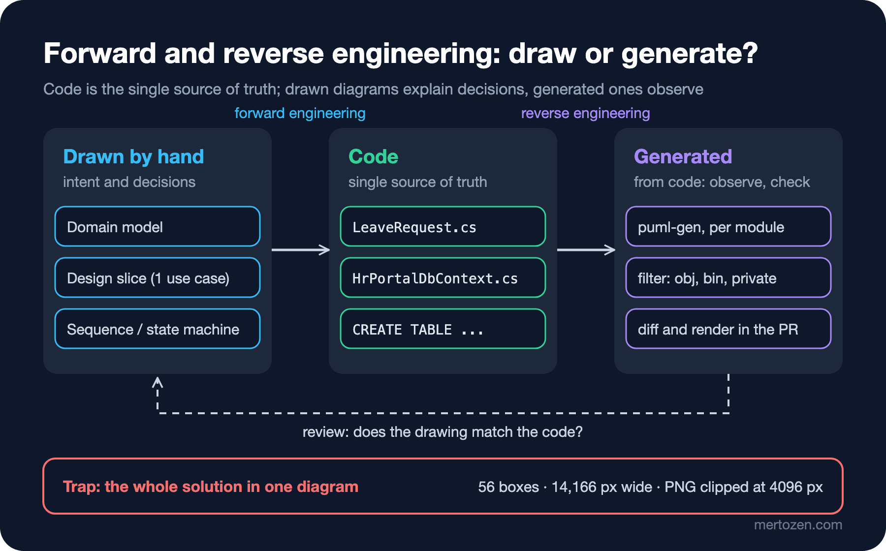
The practical rule: diagrams that explain intent and decisions are kept by hand, diagrams that observe are generated. The domain model, use cases, the design slice of a use case, sequence and state machine diagrams are drawn by hand and versioned with the code under docs/diagrams/. The job of generated diagrams is to audit the drawn ones: to answer "is there something in the code that is not in the diagram?"
Committing the generated files to the repo and regenerating them in CI makes the PR (pull request) complain when the code changes but the diagram does not:
#!/usr/bin/env bash
set -euo pipefail
dotnet tool restore > /dev/null
dotnet puml-gen src/HrPortal.Leave.Domain docs/diagrams/generated/domain \
  -dir -public -createAssociation -excludePaths "**/obj,**/bin" -allInOne > /dev/null
git diff --exit-code --stat -- docs/diagrams/generated
Someone adds a CancelledAt property to LeaveRequest and runs the script:
 docs/diagrams/generated/domain/LeaveRequest.puml | 1 +
 docs/diagrams/generated/domain/include.puml      | 1 +
 2 files changed, 2 insertions(+)
exit=1
This check does not update the hand-drawn diagram automatically; it tells the reviewer "something changed in the domain, look at the drawn diagram too." Diffs and the PR flow on the Git side are covered in the Git and GitHub series, and rendering diagrams in CI in the upcoming PlantUML post of this series.
Common Pitfalls
One giant class diagram of the whole solution. The 56-box, 14,166-pixel image from the opening tells nobody anything. A diagram should answer a question, and "everything" is not a question. If you generate, generate per module; if you draw, draw the slice of one use case.
Putting technical classes into the domain model. Once LeaveRequestRepository, HrPortalDbContext or LeaveRequestDto enters the domain model, you can no longer talk to the business with it, and analysis and design get mixed up.
Drawing foreign keys as attributes and an association on top. EmployeeId: int and an arrow to Employee say the same thing twice; in the design diagram show the relationship as an association and leave the foreign key in the code.
Trusting a generated diagram like a design document. As we saw above, the tool does not show primary constructor dependencies, invents aggregation because of = null! and draws realization as generalization. A generated diagram shows "what is in the code", not "why it is like this".
Drawing the diagram once at the start and walking away. If a hand-drawn diagram does not go into the PR together with the code, three sprints later it becomes a document that gives wrong information. Update it with the code or delete it; a stale diagram does more harm than no diagram.
When Not to Use It
Do not draw a design class diagram for simple CRUD (Create, Read, Update, Delete) screens; the EF Core entities already speak for themselves. Draw a domain model where the concepts are disputed: is "approval" a status, a record, or both? When you discuss that with the business, a domain model converges much faster than the code itself. Use puml-gen not as a permanent documentation source but as a discovery tool when you first read an existing codebase, and as a drift check in CI.
A Small Experiment
★☆☆ Add the BalanceAdjustment concept from R12 to the domain model: which classes does it associate with, and what are the multiplicities? Draw it without operations or foreign keys and render it with PlantUML.
★★☆ Run puml-gen with -createAssociation on the HrPortal.Leave.Application project. Do you get arrows showing the dependencies of LeaveRequestService? Rewrite the service with a classic constructor and private readonly fields, run it again and compare the two outputs. Which would you prefer, and why is changing the code for the sake of a diagram not a good motivation?
★★★ Turn the tools/check-diagrams.sh script into a GitHub Actions job. When the script fails, make it post a "the domain diagram needs an update" comment on the PR, and render the generated include.puml to PNG and upload it as an artifact.
In the next post we move to the two siblings of the class diagram: with object diagrams we will draw concrete instances such as req42: LeaveRequest to catch multiplicity mistakes, and with package diagrams we will draw the dependency map of the four projects in this post and make layer violations visible.