

ER Diagrams: Chen and Crow's Foot Notation, Cardinality, Optionality and from Class Diagram to Tables

An ER diagram shows which tables hold the data and the minimum and maximum number of records at both ends of every relationship: Chen suits concept conversations, Crow's Foot suits table and FK conversations. In this post we draw the leave module in both notations, show how composition, association classes and inheritance become tables with real EF Core output, and generate a Mermaid erDiagram straight from the EF Core model.
Version note: The diagrams in this post use UML (Unified Modeling Language) 2.5.1, Chen and Crow's Foot notation; the C# examples were tested with .NET 10 and Entity Framework Core (EF Core) 10.0.14, the Mermaid diagrams with Mermaid 12.3.
Guess First: Who Inserts the First Department?
The HR Portal domain model has two innocent-looking relationships. Every employee works in a department (Employee.DepartmentId, required) and every department has a director (Department.DirectorId, required). Both were drawn with multiplicity 1 in the class diagram and nobody objected in the review. The code is a one-to-one translation of the diagram:
public class Department
{
    public int Id { get; set; }
    public required string Name { get; set; }
    public int DirectorId { get; set; }
    public Employee Director { get; set; } = null!;
}

public class Employee
{
    public int Id { get; set; }
    public required string EmployeeNumber { get; set; }
    // ...
    public int DepartmentId { get; set; }
    public Department Department { get; set; } = null!;
}
You want to insert the very first rows into an empty database: the Engineering department and its director, Grace Hopper. What does EF Core do if you add both in the same SaveChanges? Would a hand-written SQL (Structured Query Language) script that inserts the department first and the employee second work? We will see the answer with the real error message in the pitfalls section; form an opinion until then, because this post is exactly about that: how many ends a relationship has, whether an end may stay empty and how that ends up in a table.
What Does an ER Diagram Answer?
An ER (Entity-Relationship) diagram describes how data is stored. The class diagram answered "which concepts exist and what behaviour do they carry?"; an ER diagram answers "which records exist, how are they linked and how many records can sit at each end of a link?". There are no operations, no visibility and no directly drawn inheritance. In return it states two things much more clearly than a class diagram: cardinality (the maximum number of records at an end) and optionality (the minimum, that is, whether the end may be empty).
The ER diagram is not one of the 14 UML diagrams. It comes from Peter Chen's 1976 paper "The Entity-Relationship Model—Toward a Unified View of Data", published in the first issue of ACM (Association for Computing Machinery) TODS (Transactions on Database Systems). Chen wanted a common language for the competing network, relational and entity set models of the time; his diagram consisted of rectangular entities and diamond-shaped relationships. The Crow's Foot notation you see more often in the industry started the same year with the fork symbol Gordon Everest called the "inverted arrow", and spread in the 1980s with the IE (Information Engineering) methodology of Clive Finkelstein and James Martin. From MySQL Workbench to Mermaid's erDiagram, most of today's tools speak Crow's Foot.
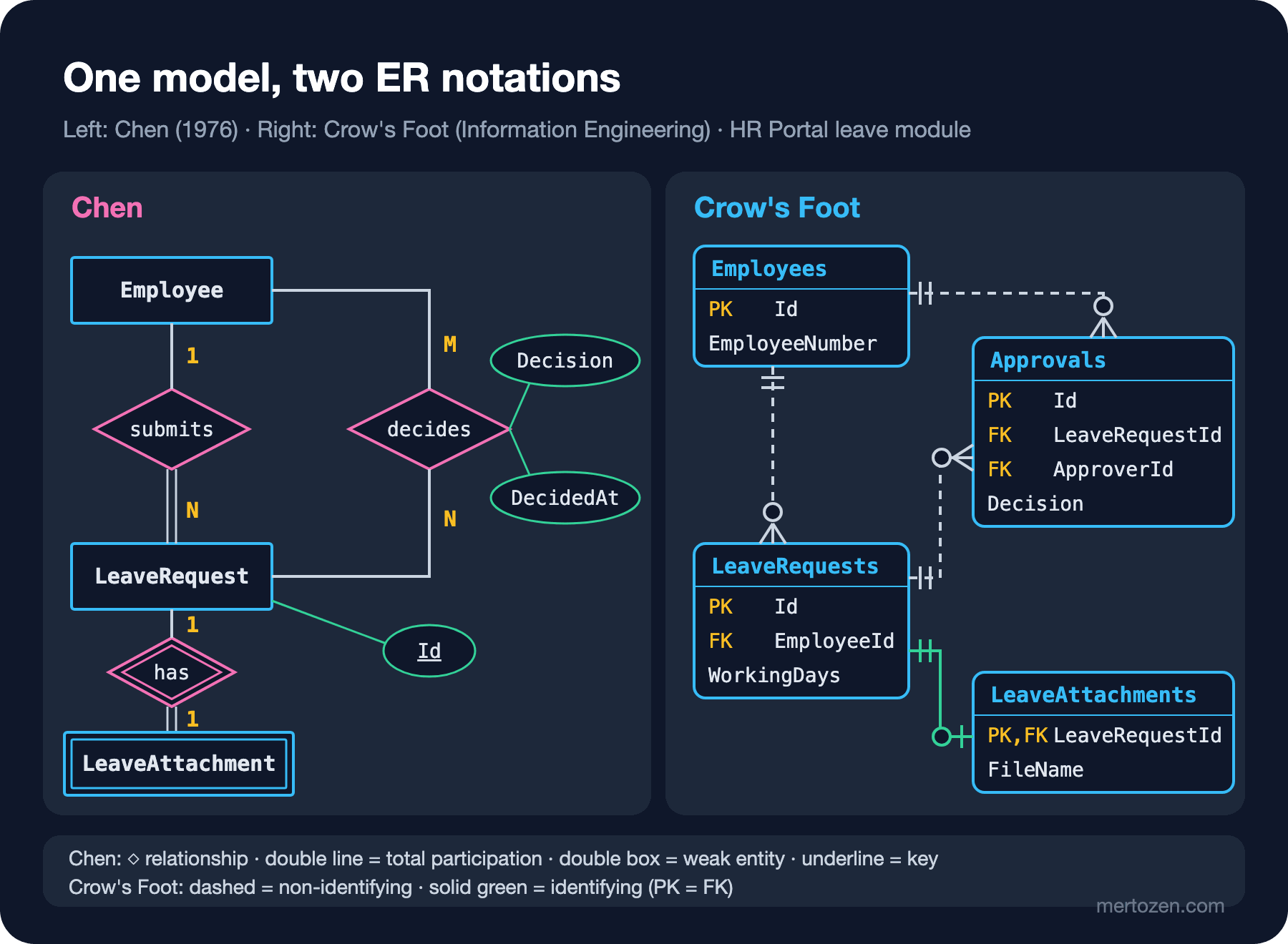
The "who are you drawing for?" question applies here too. Chen notation is good for the conceptual model, for the "how many requests can an employee have?" conversation with the business; it knows nothing about tables, columns or types. Crow's Foot is good for the logical and physical model, for talking tables, FKs (Foreign Keys) and indexes with the DBA (database administrator) and the backend team. The same model in both notations:
Chen Notation: Entity, Relationship, Attribute
In Chen every concept has its own shape. A rectangle is an entity set (Employee, LeaveRequest). A diamond is a relationship and is named with a verb (submits, decides). An oval is an attribute; an underlined oval is a key attribute. The 1, N, M labels on the edges are cardinality: an employee submits N requests, each request is submitted by exactly one employee. Textbooks have settled on a few extra symbols as well: a double line means total participation (every request must be linked to an employee), a double rectangle is a weak entity (no identity of its own) and a double diamond is the identifying relationship that ties it to its owner.
Chen's strongest point is that a relationship can carry its own attributes. decides is formed between a manager and a request, and the decision and its date belong to that relationship, not to the manager and not to the request. In this series we drew it as a UML association class (Approval); Chen says the same with a diamond that has attributes. You do not have to draw it by hand, PlantUML supports Chen notation through @startchen:
@startchen
entity Employee {
  EmployeeNumber <<key>>
  FullName
}
entity LeaveRequest {
  Id <<key>>
  WorkingDays
}
entity LeaveAttachment <<weak>> {
  FileName
}
relationship Submits {
}
relationship Decides {
  Decision
  DecidedAt
}
relationship Has <<identifying>> {
}
Employee -1- Submits
Submits =N= LeaveRequest
Employee -M- Decides
Decides -N- LeaveRequest
LeaveRequest -1- Has
Has =1= LeaveAttachment
@endchen
This source passes --check-syntax and renders with PlantUML 1.2026.9; =N= draws total participation as a thick line, <<weak>> and <<identifying>> as double-bordered shapes. Chen's weakness is just as visible: drawing an oval for every attribute of a ten-table model makes the diagram unreadable. So use Chen for concept conversations on a fragment of a few entities, and switch to Crow's Foot once you are down to tables.
Crow's Foot: Reading Cardinality and Optionality from One Symbol
In Crow's Foot an entity is a table box with its attributes listed line by line inside. A relationship is a single line; the meaning is in the marks at its two ends. Each end has two marks: the one next to the entity gives the maximum, the one further out gives the minimum. A fork means "many", a bar means "one", a ring means "zero".
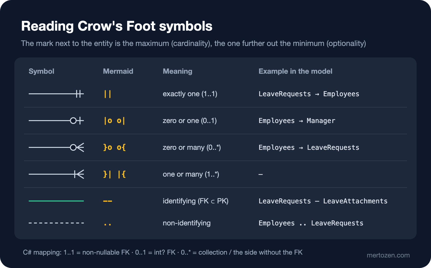
The reading direction is the same as UML multiplicity: the mark next to an entity says how many of that entity a single record on the other side sees. In Employees ||..o{ LeaveRequests, the o{ on the LeaveRequests side means "an employee has zero or many requests", the || on the Employees side means "every request has exactly one employee". The second sentence is visible directly in SQL: EmployeeId int NOT NULL. In a table, optionality is whether the FK column is nullable; because ManagerId int NULL, the relationship between an employee and their manager is drawn with |o.
Mermaid's erDiagram syntax turns these marks into ASCII (American Standard Code for Information Interchange) characters almost one to one. A slice of the model we use in the series:
erDiagram
    Employees ||..o{ LeaveRequests : "EmployeeId"
    LeaveTypes ||..o{ LeaveRequests : "LeaveTypeId"
    LeaveRequests ||..o{ Approvals : "LeaveRequestId (cascade)"
    Employees ||..o{ Approvals : "ApproverId"
    LeaveRequests ||--o| LeaveAttachments : "LeaveRequestId (cascade)"
    LeaveRequests {
        int Id PK
        int EmployeeId FK
        int LeaveTypeId FK
        date Period_Start
        date Period_End
        int WorkingDays
        nvarchar(30) Status
    }
    LeaveAttachments {
        int LeaveRequestId PK, FK
        nvarchar(255) FileName
}PK, FK and UK mark a Primary Key, a Foreign Key and a Unique Key; a column can carry two of them, as in PK, FK. Since Mermaid 11.16 you can also mark a nullable column with a trailing ? on the type (int? ManagerId). This block renders without errors with Mermaid CLI (Command-Line Interface) 12.2.0 (Mermaid 12.3.0).
Identifying and Non-Identifying Relationships, Weak and Associative Entities
The Mermaid source above uses two different lines: .. and --. The Mermaid documentation defines them as non-identifying and identifying relationships and draws them dashed and solid. The distinction: if the child table's FK is part of its own PK (Primary Key), the relationship is identifying and the child takes its identity from its parent. If the FK is an ordinary column, the relationship is non-identifying.
The PK of LeaveAttachments is LeaveRequestId, and the same column is the FK to LeaveRequests. The attachment has no identity of its own; it is defined as "the attachment of request 42". That is exactly Chen's weak entity. Approvals, on the other hand, has its own Id, and LeaveRequestId is an ordinary FK, so that relationship is non-identifying. This is a design decision: with (LeaveRequestId, Step) as the PK of Approvals, the relationship would be identifying. In .NET projects that use surrogate keys (an artificial Id) almost every relationship ends up non-identifying; you usually meet identifying relationships in owned types, junction tables and TPT (Table-per-Type) inheritance.
An associative entity is an M:N (many-to-many) relationship turned into a table together with its own attributes. Chen's decides diamond and UML's Approval association class become the Approvals table with two FKs in Crow's Foot. For a many-to-many without payload (just two FKs) EF Core creates the junction table itself; with a payload you write the entity explicitly. We covered the EF side in the EF Core series post "Relationships 2: One-to-One, Many-to-Many and UsingEntity".
From Class Diagram to Tables: Four Transformations
Every relationship type in a class diagram has a counterpart in tables, and EF Core reads that counterpart from configuration. The relevant part of the HR Portal HrPortalDbContext:
b.Entity<LeaveRequest>(e =>
{
    e.ComplexProperty(x => x.Period);
    e.Property(x => x.Status).HasConversion<string>().HasMaxLength(30);
    // Association: deleting the requester must not delete the request
    e.HasOne(x => x.Employee).WithMany().HasForeignKey(x => x.EmployeeId)
        .OnDelete(DeleteBehavior.Restrict);
    // Composition: the attachment is part of the request, own table but no identity of its own
    e.OwnsOne(x => x.Attachment, a =>
    {
        a.ToTable("LeaveAttachments");
        a.Property(p => p.FileName).HasMaxLength(255);
    });
    // Composition: approvals cannot exist without the request
    e.HasMany(x => x.Approvals).WithOne().HasForeignKey(x => x.LeaveRequestId)
        .OnDelete(DeleteBehavior.Cascade);
});

b.Entity<Approval>(e =>
{
    e.HasIndex(x => new { x.LeaveRequestId, x.Step }).IsUnique();
    e.HasOne(x => x.Approver).WithMany().HasForeignKey(x => x.ApproverId)
        .OnDelete(DeleteBehavior.Restrict);
});

b.Entity<LeaveBalance>(e =>
{
    // Derived attribute (/RemainingDays) -> computed column
    e.Property(x => x.RemainingDays).HasComputedColumnSql("[EntitledDays] - [UsedDays]");
    e.HasIndex(x => new { x.EmployeeId, x.LeaveTypeId, x.Year }).IsUnique();
});
db.Database.GenerateCreateScript() produces the SQL Server DDL (Data Definition Language) of this model without connecting to a database. The relevant lines of the output:
CREATE TABLE [LeaveAttachments] (
    [LeaveRequestId] int NOT NULL,
    [FileName] nvarchar(255) NOT NULL,
    [ContentType] nvarchar(100) NOT NULL,
    [StoragePath] nvarchar(400) NOT NULL,
    CONSTRAINT [PK_LeaveAttachments] PRIMARY KEY ([LeaveRequestId]),
    CONSTRAINT [FK_LeaveAttachments_LeaveRequests_LeaveRequestId] FOREIGN KEY ([LeaveRequestId]) REFERENCES [LeaveRequests] ([Id]) ON DELETE CASCADE
);

CREATE TABLE [LeaveBalances] (
    /* ... */
    [RemainingDays] AS [EntitledDays] - [UsedDays],
    /* ... */
);

CREATE UNIQUE INDEX [IX_Approvals_LeaveRequestId_Step] ON [Approvals] ([LeaveRequestId], [Step]);
ALTER TABLE [Approvals] ADD CONSTRAINT [FK_Approvals_Employees_ApproverId] FOREIGN KEY ([ApproverId]) REFERENCES [Employees] ([Id]) ON DELETE NO ACTION;
ALTER TABLE [Approvals] ADD CONSTRAINT [FK_Approvals_LeaveRequests_LeaveRequestId] FOREIGN KEY ([LeaveRequestId]) REFERENCES [LeaveRequests] ([Id]) ON DELETE CASCADE;
Side by side, the rule becomes visible:
| Class diagram | ER diagram | Table (SQL Server) |
|---|---|---|
Association 1 ↔ 0..* | ||..o{, non-identifying | NOT NULL FK on the many side, ON DELETE NO ACTION |
Association 0..1 ↔ 0..* | |o..o{ | Nullable FK (ManagerId int NULL) |
| Composition (filled diamond) | FK with cascade; identifying ||--o| when an owned type gets its own table | ON DELETE CASCADE, PK = FK for the owned type |
| Association class | Associative entity | Table with two FKs, payload columns, a unique index if needed |
| Generalization | Not drawn; table(s) depend on the mapping strategy | TPH (Table-per-Hierarchy): one table + discriminator; TPT: subtype tables with PK = FK |
Derived attribute (/RemainingDays) | A computed column or no column at all | AS [EntitledDays] - [UsedDays] |
Note that EF Core's Restrict is generated as ON DELETE NO ACTION on SQL Server; SQL Server has no RESTRICT referential action, and NO ACTION does the same job through the constraint check. Composition turning into cascade is where UML and the database meet most clearly: the part lives with the whole and is deleted with the whole.
Inheritance is not drawn directly in an ER diagram, because the relational model has no inheritance; the mapping strategy you choose decides the table layout. We deliberately kept LeaveType as a lookup entity, but what if leave types were modelled as a class hierarchy? A small experimental model:
public abstract class LeaveRequestBase
{
    public int Id { get; set; }
    public int WorkingDays { get; set; }
}

public class AnnualLeaveRequest : LeaveRequestBase
{
    public int BalanceYear { get; set; }
}

public class SickLeaveRequest : LeaveRequestBase
{
    public string? MedicalReportPath { get; set; }
}

// Default strategy: TPH (one table + Discriminator)
public class TphContext : HierarchyContext;

public class TptContext : HierarchyContext
{
    protected override void OnModelCreating(ModelBuilder b)
    {
        base.OnModelCreating(b);
        b.Entity<LeaveRequestBase>().UseTptMappingStrategy();
    }
}
The ER generated from the two contexts' models (with the generator we write below):
-- TPH
erDiagram
    LeaveRequests {
        int Id PK
        int? BalanceYear
        nvarchar(21) Discriminator
        nvarchar(max)? MedicalReportPath
        int WorkingDays
    }

-- TPT
erDiagram
    AnnualLeaveRequest {
        int Id PK, FK
        int BalanceYear
    }
    LeaveRequests {
        int Id PK
        int WorkingDays
    }
    SickLeaveRequest {
        int Id PK, FK
        nvarchar(max)? MedicalReportPath
    }
    LeaveRequests ||--o| AnnualLeaveRequest : "Id (cascade)"
    LeaveRequests ||--o| SickLeaveRequest : "Id (cascade)"
TPH (Table-per-Hierarchy) produces a single table and pays for it in optionality: BalanceYear is an int in C# but int? in the column, because it must stay empty on sick leave rows. TPT (Table-per-Type) produces a table per subtype, and the relationship between a subtype table and the base table is an identifying 1:0..1: SickLeaveRequest.Id is both PK and FK. In other words, TPT is drawn with weak entities in an ER diagram. We measured when to choose which in the EF Core series post "Inheritance Mapping: TPH, TPT and When to Choose Which".
Generating a Mermaid erDiagram from the EF Core Model
The worst enemy of an ER diagram is going stale. You add a column with a migration and forget the diagram. The table-level ER already lives in code: the EF Core model that produces the migrations. So instead of drawing it by hand, it makes sense to generate it from the model. EF Core's relational model API (IModel.GetRelationalModel()) exposes the table, column and FK information that migrations use too:
using System.Text;
using Microsoft.EntityFrameworkCore;
using Microsoft.EntityFrameworkCore.Metadata;
using Microsoft.EntityFrameworkCore.Migrations;

namespace HrPortal.Tools;

public static class MermaidErWriter
{
    public static string Write(IModel model)
    {
        var sb = new StringBuilder("erDiagram\n");
        var tables = model.GetRelationalModel().Tables.OrderBy(t => t.Name).ToList();

        foreach (var table in tables)
        {
            var pk = table.PrimaryKey!.Columns;
            sb.AppendLine($"    {table.Name} {{");
            foreach (var column in table.Columns)
            {
                List<string> keys = [];
                if (pk.Contains(column)) keys.Add("PK");
                if (table.ForeignKeyConstraints.Any(fk => fk.Columns.Contains(column))) keys.Add("FK");
                if (table.Indexes.Any(i => i.IsUnique && i.Columns.Contains(column))) keys.Add("UK");
                var type = column.StoreType.Replace(" ", "") + (column.IsNullable ? "?" : "");
                List<string> parts = [type, column.Name];
                if (keys.Count > 0) parts.Add(string.Join(", ", keys));
                if (column.ComputedColumnSql is { } sql) parts.Add($"\"computed: {sql}\"");
                sb.AppendLine("        " + string.Join(" ", parts));
            }
            sb.AppendLine("    }");
        }

        foreach (var table in tables)
        {
            var pk = table.PrimaryKey!.Columns;
            foreach (var fk in table.ForeignKeyConstraints.OrderBy(f => f.Name))
            {
                // Principal side: 0..1 if the FK is nullable, otherwise exactly 1
                var left = fk.Columns.Any(c => c.IsNullable) ? "|o" : "||";
                // Dependent side: at most 1 if the FK is unique, otherwise many
                var unique = fk.Columns.SequenceEqual(pk)
                    || table.Indexes.Any(i => i.IsUnique && i.Columns.SequenceEqual(fk.Columns));
                var right = unique ? "o|" : "o{";
                // Identifying (solid) if the FK is part of the PK, otherwise non-identifying (dashed)
                var line = fk.Columns.All(pk.Contains) ? "--" : "..";
                var rule = fk.OnDeleteAction == ReferentialAction.Cascade ? "cascade" : "restrict";
                var by = string.Join(",", fk.Columns.Select(c => c.Name));
                sb.AppendLine($"    {fk.PrincipalTable.Name} {left}{line}{right} {table.Name} : \"{by} ({rule})\"");
            }
        }
        return sb.ToString();
    }
}
The code applies the rules we discussed from the start of the post one to one: a nullable FK gives |o on the principal side, a unique FK gives o| on the dependent side, an FK that is part of the PK gives a solid line. No connection string is needed, options built with UseSqlServer are enough; the model is built without touching a database. The relationship part of a real run:
    Employees ||..o{ Approvals : "ApproverId (restrict)"
    LeaveRequests ||..o{ Approvals : "LeaveRequestId (cascade)"
    Employees ||..o{ BalanceAdjustments : "AdjustedById (restrict)"
    LeaveBalances ||..o{ BalanceAdjustments : "LeaveBalanceId (cascade)"
    Employees ||..o{ Departments : "DirectorId (restrict)"
    Departments ||..o{ Employees : "DepartmentId (restrict)"
    Employees |o..o{ Employees : "ManagerId (restrict)"
    LeaveRequests ||--o| LeaveAttachments : "LeaveRequestId (cascade)"
    Employees ||..o{ LeaveBalances : "EmployeeId (restrict)"
    LeaveTypes ||..o{ LeaveBalances : "LeaveTypeId (restrict)"
    Employees ||..o{ LeaveRequests : "EmployeeId (restrict)"
    LeaveTypes ||..o{ LeaveRequests : "LeaveTypeId (restrict)"
and the LeaveBalances box:
    LeaveBalances {
        int Id PK
        int EmployeeId FK, UK
        int EntitledDays
        int LeaveTypeId FK, UK
        int RemainingDays "computed: [EntitledDays] - [UsedDays]"
        int UsedDays
        int Year UK
    }
The generated file renders with mmdc as a nine-table diagram. Know its two limits: the relational model returns columns sorted by name, not in table order; and Mermaid has no notion of a composite unique key, so the (EmployeeId, LeaveTypeId, Year) triple shows up as three separate UK marks. The generated diagram is the physical model; it does not replace the conceptual model, that is Chen or the domain class diagram. We will keep this file in the repo and check in CI (Continuous Integration) that it is up to date in the series finale.
Common Pitfalls
Building a cycle out of mandatory relationships. Back to the opening question. The real result of adding the department and its director in the same SaveChanges:
Unable to save changes because a circular dependency was detected in the data to be saved: 'Department [Added] <-
ForeignKeyConstraint { 'DepartmentId' } Employee [Added] <-
ForeignKeyConstraint { 'DirectorId' } Department [Added]To show additional information call 'DbContextOptionsBuilder.EnableSensitiveDataLogging'.'.
Hand-written SQL does not save you either: inserting the department needs the Id of an existing employee, inserting the employee needs the Id of an existing department, and both columns are NOT NULL. SQL Server has no deferred constraints, so the first row can never be inserted. In the ER diagram this is a cycle with || on both ends, and the bug was in the diagram, not in the code. The fix is to make one end of the cycle optional: Department.DirectorId becomes int?, it is drawn as Employees |o..o{ Departments in the ER diagram and the rows go in in two steps:
await using var tx = await db.Database.BeginTransactionAsync();
// 1) The department is inserted without a director (DirectorId NULL)
var engineering = new Department { Name = "Engineering" };
db.Add(engineering);
await db.SaveChangesAsync();

// 2) The employee is inserted and assigned as the department's director
var grace = new Employee
{
    EmployeeNumber = "E-0007", FullName = "Grace Hopper", Email = "grace@example.com",
    Department = engineering
};
engineering.Director = grace;
await db.SaveChangesAsync();
await tx.CommitAsync();

Console.WriteLine($"Department {engineering.Id}: director {engineering.DirectorId}; employee {grace.Id}: department {grace.DepartmentId}");
Department 1: director 1; employee 1: department 1This means accepting "a department without a director" as a business state in the model, and that has to be discussed with the business. Leaving a cycle that is readable from the diagram to the code, without changing the model, is next sprint's bug.
Mistaking the physical model for the conceptual one. The Approvals table, the RemainingDays computed column and complex type columns like Period_Start are physical decisions. Show the generated ER to the business and the meeting ends with "what is Period_End?". Chen or the domain model for concept conversations, Crow's Foot for table conversations.
Drawing optionality without looking at the FK. Drawing || in the diagram and leaving the column nullable (or the other way round) is the most common inconsistency. Generating the diagram from the model removes this class of error, because the mark comes straight from IsNullable.
Putting cascade everywhere. On an association that is not a composition, cascade means that deleting an employee deletes every record they approved. SQL Server also rejects more than one cascade path to the same table (multiple cascade paths). Use cascade only where the filled diamond is.
Treating ER as a normalisation tool. An ER diagram shows the existing structure; it does not tell you why a table should be split in two. Normal forms and physical data model decisions are the topic of the upcoming Data Modeling and Normalization series.
A Small Experiment
★☆☆ Draw BalanceAdjustment in Chen notation. Is it a weak entity or an entity with its own identity? Justify your decision by looking at the PK of the BalanceAdjustments table and render it with PlantUML's @startchen syntax.
★★☆ Add composite unique index support to the generator in this post: write indexes such as (EmployeeId, LeaveTypeId, Year) as an attribute comment or a Mermaid comment line instead of a UK per column. Render the output with mmdc and verify it is still valid.
★★★ Make (LeaveRequestId, Step) the PK of Approvals and remove Id. How did the line drawn by the generator change? Inspect the SQL the migration produces and write down how this change affects the GET /leave-requests/{id} response of the API, change tracking in EF Core and a future "second approval in the same step" requirement.
In this post we generated an ER diagram from code instead of drawing it by hand for the first time. The next post extends the same idea to every diagram: diagrams as code with PlantUML, the source files of the series' use case, class, sequence, state and C4 (Context, Containers, Components, Code) diagrams, !include for a shared style, C4-PlantUML, and checking and rendering the diagrams in a PR (pull request) with GitHub Actions.